Tobe82
Experto
Cambiando cadena de tiempo de un chrysler 300 3.6L
TIMING CHAIN, REPLACE
Chrysler 300 3.6L V6 ERB 2011/2014
1.Remove engine cover.
2.Disconnect electrical connector from Inlet Air Temperature (IAT) sensor.
3.Loosen clamp and remove air inlet hose from resonator.
4.Remove push pin and pull resonator straight up from two locating pins on righthand valve cover, then disengage resonator from throttle body inlet.
5.Disconnect electrical connectors from Manifold Absolute Pressure (MAP) sensor and Electronic Throttle Control (ETC).
6.Disengage ETC harness from clip on throttle body and retainers on upper intake manifold, near MAP sensor, then reposition wire harness.
7.Disconnect Positive Crankcase Ventilation (PCV) hose, vapor purge hose and brake booster hose from upper intake manifold.
8.Disengage wire harness retainer from upper intake manifold support bracket.
9.Disengage wire harness retainer from support bracket studbolt.
10.Remove two nuts, loosen studbolt and reposition upper intake manifold support bracket.
11.Remove nut from heater core return tube support bracket.
12.Remove two nuts, loosen two studbolts and reposition two upper intake manifold support brackets.
13.Remove seven mounting bolts and remove upper intake manifold. Upper intake manifold bolts are captured in upper intake manifold. Once loosened, bolts will have to be lifted out of lower intake manifold and held while removing upper intake manifold. Do not inadvertently loosen two fuel rail attachment bolts that are in close proximity of upper intake manifold attaching bolts.
14.Remove and discard six upper to lower intake manifold seals.
15.Remove lefthand and righthand valve covers.
16.Remove spark plugs.
17.Raise and support vehicle.
18.Drain cooling system and engine oil into suitable containers.
19.Remove upper oil pan.
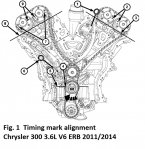
20.Rotate crankshaft clockwise (as viewed from front) to place number one cylinder piston at TDC on exhaust stroke by aligning dimple (4) on crankshaft with block/bearing cap junction (5), Fig. 1.
21.While maintaining this alignment, verify that arrows (2) on lefthand cam phasers point toward each other and are parallel to cylinder head cover mounting surface (3) and that righthand cam phaser arrows (7) point away from each other and scribe lines (9) are parallel to cylinder head cover mounting surface (8), Fig. 1.
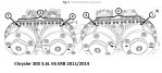
22.There should be twelve chain pins (2) between exhaust cam phaser triangle marking (1) and intake cam phaser circle marking (3) as viewed from either front or rear of cam phasers, Fig. 2. Phaser markings (1 and 3) could align with either an external or internal chain link. Either alignment is acceptable as long as there are twelve chain pins between markings.
23.Mark direction of rotation on lefthand cam chain, righthand cam chain, oil pump chain and primary chain using a paint pen or equivalent to aid in assembly. Always install timing chains so that they maintain same direction of rotation. Inverting a previously run chain on a previously run sprocket will result in excessive wear to both chain and sprocket.
24.Reset righthand cam chain tensioner by pushing back tensioner piston and installing tensioner pin tool No. 8514, or equivalent.
25.Reset lefthand cam chain tensioner by lifting pawl, pushing back piston and installing tensioner pin tool No. 8514, or equivalent.
26.Remove mounting bolts and timing gear splash shield.
27.Disengage oil pump chain tensioner spring from dowel pin and remove oil pump chain tensioner.
28.Remove oil pump sprocket T45 retaining bolt and remove oil pump sprocket and oil pump chain.
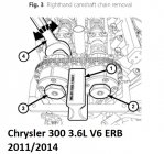
29.Install righthand camshaft/phaser lock tool No. 10202-1 (1) with tool number facing up, Fig. 3. Rocking camshaft slightly (a few degrees) with a wrench (4) may be required when installing camshaft phaser lock.
30.Loosen, but do not remove, exhaust oil control valve (3) and intake oil control valve (2), Fig. 3.
31.Remove righthand camshaft/phaser lock tool No. 10202-1 (1), Fig. 3.
32.Remove oil control valve (2) from righthand intake cam phaser, Fig. 3.
33.Pull righthand intake cam phaser off of camshaft and remove righthand cam chain.
34.Remove oil control valve (3) and pull righthand exhaust cam phaser off from camshaft, as required, Fig. 3.
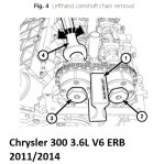
35.Install lefthand camshaft/phaser lock tool No. 10202-2 (1) with tool number facing up, Fig. 4. Rocking camshaft slightly (a few degrees) with a wrench (4) may be required when installing camshaft phaser lock.
36.Loosen, but do not remove, exhaust oil control valve (2) and intake oil control valve (3), Fig. 4.
37.Remove lefthand camshaft/phaser lock tool No. 10202-2 (1), Fig. 4.
38.Remove oil control valve (2) from lefthand exhaust cam phaser, Fig. 4.
39.Pull lefthand exhaust cam phaser off of camshaft and remove lefthand cam chain.
40.Remove oil control valve (3) and pull lefthand intake cam phaser off of camshaft, as required. Fig. 4.
41.Reset primary chain tensioner by pushing back tensioner piston and installing tensioner pin tool No. 8514, or equivalent.
42.Remove two T30 bolts and remove primary chain tensioner.
43.Remove T30 bolt and primary chain guide.
44.Remove idler sprocket T45 retaining bolt and washer.
45.Remove primary chain, idler sprocket and crankshaft sprocket as an assembly.
46.Remove two T30 bolts and lefthand cam chain tensioner, as required.
47.Remove two T30 bolts and lefthand cam chain guide and tensioner arm, as required.
48.Remove two T30 bolts and righthand cam chain tensioner, as required.
49.Remove three T30 bolts and righthand cam chain guide and tensioner arm, as required.
50.Inspect all sprockets and chain guides. Replace if damaged.
51.Reverse procedure to install, note following:
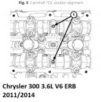
a.Verify that camshafts are set at TDC by positioning alignment holes (1) vertically, Fig. 5. Do not rotate camshafts more than a few degrees independently of crankshaft. Valve to piston contact could occur resulting in possible valve damage. If camshafts need to be rotated more than a few degrees, first move pistons away from cylinder heads by rotating crankshaft counterclockwise to a position 30° BTDC. Once camshafts are returned to their TDC position, rotate crankshaft clockwise to return crankshaft to TDC.
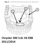
b.Place primary chain onto crankshaft sprocket (3) so that arrow (2) is aligned with plated link (1) on timing chain, Fig. 6. Always install timing chains so that they maintain same direction of rotation. Inverting a previously run chain on a previously run sprocket will result in excessive wear to both chain and sprocket.
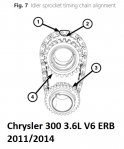
c.While maintaining this alignment, invert crankshaft sprocket and timing chain and place idler sprocket (4) into timing chain so that dimple (2) is aligned with plated link (1) on timing chain, Fig. 7.
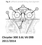
d.While maintaining this alignment, route cam chain around exhaust and intake cam phasers so that plated links are aligned with phaser timing marks (1). Position lefthand cam phasers so that arrows (3) point toward each other and are parallel to cylinder head cover mounting surface (5). Press exhaust cam phaser onto exhaust cam, install and hand tighten oil control valve (2), Fig. 8.
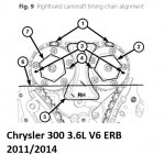
e.While maintaining this alignment, route cam chain around exhaust and intake cam phasers so that plated links are aligned with phaser timing marks (1). Position righthand cam phasers so that arrows (3) point away from each other and scribe lines (4) are parallel to valve cover mounting surface (6). Press intake cam phaser onto intake cam, install and hand tighten oil control valve (2), Fig. 9.
f.Torque timing chain guide to 106 inch lbs.
g.Torque timing chain idler sprocket to 18 ft. lbs.
h.Torque timing chain tensioner to 106 inch lbs.
i.Torque timing gear splash shield to 35 inch lbs.
TIMING CHAIN, REPLACE
Chrysler 300 3.6L V6 ERB 2011/2014
1.Remove engine cover.
2.Disconnect electrical connector from Inlet Air Temperature (IAT) sensor.
3.Loosen clamp and remove air inlet hose from resonator.
4.Remove push pin and pull resonator straight up from two locating pins on righthand valve cover, then disengage resonator from throttle body inlet.
5.Disconnect electrical connectors from Manifold Absolute Pressure (MAP) sensor and Electronic Throttle Control (ETC).
6.Disengage ETC harness from clip on throttle body and retainers on upper intake manifold, near MAP sensor, then reposition wire harness.
7.Disconnect Positive Crankcase Ventilation (PCV) hose, vapor purge hose and brake booster hose from upper intake manifold.
8.Disengage wire harness retainer from upper intake manifold support bracket.
9.Disengage wire harness retainer from support bracket studbolt.
10.Remove two nuts, loosen studbolt and reposition upper intake manifold support bracket.
11.Remove nut from heater core return tube support bracket.
12.Remove two nuts, loosen two studbolts and reposition two upper intake manifold support brackets.
13.Remove seven mounting bolts and remove upper intake manifold. Upper intake manifold bolts are captured in upper intake manifold. Once loosened, bolts will have to be lifted out of lower intake manifold and held while removing upper intake manifold. Do not inadvertently loosen two fuel rail attachment bolts that are in close proximity of upper intake manifold attaching bolts.
14.Remove and discard six upper to lower intake manifold seals.
15.Remove lefthand and righthand valve covers.
16.Remove spark plugs.
17.Raise and support vehicle.
18.Drain cooling system and engine oil into suitable containers.
19.Remove upper oil pan.
20.Rotate crankshaft clockwise (as viewed from front) to place number one cylinder piston at TDC on exhaust stroke by aligning dimple (4) on crankshaft with block/bearing cap junction (5), Fig. 1.
21.While maintaining this alignment, verify that arrows (2) on lefthand cam phasers point toward each other and are parallel to cylinder head cover mounting surface (3) and that righthand cam phaser arrows (7) point away from each other and scribe lines (9) are parallel to cylinder head cover mounting surface (8), Fig. 1.
22.There should be twelve chain pins (2) between exhaust cam phaser triangle marking (1) and intake cam phaser circle marking (3) as viewed from either front or rear of cam phasers, Fig. 2. Phaser markings (1 and 3) could align with either an external or internal chain link. Either alignment is acceptable as long as there are twelve chain pins between markings.
23.Mark direction of rotation on lefthand cam chain, righthand cam chain, oil pump chain and primary chain using a paint pen or equivalent to aid in assembly. Always install timing chains so that they maintain same direction of rotation. Inverting a previously run chain on a previously run sprocket will result in excessive wear to both chain and sprocket.
24.Reset righthand cam chain tensioner by pushing back tensioner piston and installing tensioner pin tool No. 8514, or equivalent.
25.Reset lefthand cam chain tensioner by lifting pawl, pushing back piston and installing tensioner pin tool No. 8514, or equivalent.
26.Remove mounting bolts and timing gear splash shield.
27.Disengage oil pump chain tensioner spring from dowel pin and remove oil pump chain tensioner.
28.Remove oil pump sprocket T45 retaining bolt and remove oil pump sprocket and oil pump chain.
29.Install righthand camshaft/phaser lock tool No. 10202-1 (1) with tool number facing up, Fig. 3. Rocking camshaft slightly (a few degrees) with a wrench (4) may be required when installing camshaft phaser lock.
30.Loosen, but do not remove, exhaust oil control valve (3) and intake oil control valve (2), Fig. 3.
31.Remove righthand camshaft/phaser lock tool No. 10202-1 (1), Fig. 3.
32.Remove oil control valve (2) from righthand intake cam phaser, Fig. 3.
33.Pull righthand intake cam phaser off of camshaft and remove righthand cam chain.
34.Remove oil control valve (3) and pull righthand exhaust cam phaser off from camshaft, as required, Fig. 3.
35.Install lefthand camshaft/phaser lock tool No. 10202-2 (1) with tool number facing up, Fig. 4. Rocking camshaft slightly (a few degrees) with a wrench (4) may be required when installing camshaft phaser lock.
36.Loosen, but do not remove, exhaust oil control valve (2) and intake oil control valve (3), Fig. 4.
37.Remove lefthand camshaft/phaser lock tool No. 10202-2 (1), Fig. 4.
38.Remove oil control valve (2) from lefthand exhaust cam phaser, Fig. 4.
39.Pull lefthand exhaust cam phaser off of camshaft and remove lefthand cam chain.
40.Remove oil control valve (3) and pull lefthand intake cam phaser off of camshaft, as required. Fig. 4.
41.Reset primary chain tensioner by pushing back tensioner piston and installing tensioner pin tool No. 8514, or equivalent.
42.Remove two T30 bolts and remove primary chain tensioner.
43.Remove T30 bolt and primary chain guide.
44.Remove idler sprocket T45 retaining bolt and washer.
45.Remove primary chain, idler sprocket and crankshaft sprocket as an assembly.
46.Remove two T30 bolts and lefthand cam chain tensioner, as required.
47.Remove two T30 bolts and lefthand cam chain guide and tensioner arm, as required.
48.Remove two T30 bolts and righthand cam chain tensioner, as required.
49.Remove three T30 bolts and righthand cam chain guide and tensioner arm, as required.
50.Inspect all sprockets and chain guides. Replace if damaged.
51.Reverse procedure to install, note following:
a.Verify that camshafts are set at TDC by positioning alignment holes (1) vertically, Fig. 5. Do not rotate camshafts more than a few degrees independently of crankshaft. Valve to piston contact could occur resulting in possible valve damage. If camshafts need to be rotated more than a few degrees, first move pistons away from cylinder heads by rotating crankshaft counterclockwise to a position 30° BTDC. Once camshafts are returned to their TDC position, rotate crankshaft clockwise to return crankshaft to TDC.
b.Place primary chain onto crankshaft sprocket (3) so that arrow (2) is aligned with plated link (1) on timing chain, Fig. 6. Always install timing chains so that they maintain same direction of rotation. Inverting a previously run chain on a previously run sprocket will result in excessive wear to both chain and sprocket.
c.While maintaining this alignment, invert crankshaft sprocket and timing chain and place idler sprocket (4) into timing chain so that dimple (2) is aligned with plated link (1) on timing chain, Fig. 7.
d.While maintaining this alignment, route cam chain around exhaust and intake cam phasers so that plated links are aligned with phaser timing marks (1). Position lefthand cam phasers so that arrows (3) point toward each other and are parallel to cylinder head cover mounting surface (5). Press exhaust cam phaser onto exhaust cam, install and hand tighten oil control valve (2), Fig. 8.
e.While maintaining this alignment, route cam chain around exhaust and intake cam phasers so that plated links are aligned with phaser timing marks (1). Position righthand cam phasers so that arrows (3) point away from each other and scribe lines (4) are parallel to valve cover mounting surface (6). Press intake cam phaser onto intake cam, install and hand tighten oil control valve (2), Fig. 9.
f.Torque timing chain guide to 106 inch lbs.
g.Torque timing chain idler sprocket to 18 ft. lbs.
h.Torque timing chain tensioner to 106 inch lbs.
i.Torque timing gear splash shield to 35 inch lbs.
Adjuntos
-
 chrysler_300_36_timingchain_1.jpg215,5 KB · Visitas: 1.048
 -
 chrysler_300_36_timingchain_2.jpg201,4 KB · Visitas: 822
 -
 chrysler_300_36_timingchain_3.jpg101,8 KB · Visitas: 895
 -
 chrysler_300_36_timingchain_4.jpg101,4 KB · Visitas: 650
 -
 chrysler_300_36_timingchain_5.jpg104,2 KB · Visitas: 723
 -
 chrysler_300_36_timingchain_6.jpg89 KB · Visitas: 735
 -
 chrysler_300_36_timingchain_7.jpg63 KB · Visitas: 919
 -
 chrysler_300_36_timingchain_8.jpg93,4 KB · Visitas: 2.930
 -
 chrysler_300_36_timingchain_9.jpg96,8 KB · Visitas: 867