-
Hola Invitado, Foromecanicos es el Foro de Automecanico y Autoelectronico - informacion sobre mecanica automotriz, computers, encendido y auto electronics, diagramas.
Estás utilizando un navegador obsoleto. Este u otros sitios web pueden no ser mostrados correctamente.
Debes actualizarlo o utilizar un navegador alternativo.
Debes actualizarlo o utilizar un navegador alternativo.
Diagrama De Tiempo Crossfire 05
- Iniciador del tema gruizrmz
- Fecha de inicio
Tobe82
Experto
Esquemas para cadena de tiempo Crossfire 3.2L 2004-2008
TIMING CHAIN, REPLACE
1.Relieve fuel pressure as follows:
a.Remove fuel pump relay form power distribution center.
b.Start and run engine until it stalls.
c.Attempt to start engine until it no longer runs.
d.Turn ignition switch to Off position.
e.Place suitable rag or shop towel under fuel line quick-connector fitting at fuel rail.
f.Install fuel pump relay.
g.One or more Diagnostic Trouble Codes (DTCs) may have been stored because of removing fuel pump relay. Clear these DTCs with suitably programmed scan tool.
2.Remove air cleaner assembly housing.
3.Drain engine coolant into suitable container.
4.Remove cooling fan.
5.Remove radiator as follows:
a.Remove air cleaner inlet tubes.
b.Disconnect upper, lower and coolant recovery reservoir hoses.
c.On models equipped with automatic transmission, disconnect transmission fluid cooler lines, then plug openings to prevent leakage and contamination.
d.On all models, remove two radiator hold-down clamps.
e.Tilt radiator forward and remove A/C condenser to radiator retaining bolts.
f.Remove radiator from vehicle.
6.Remove serpentine drive belt.
7.Disconnect mass air flow sensor connector and retaining screws, then remove sensor.
8.Disconnect brake vacuum booster, intake manifold inspect valve and purge vacuum valve hoses.
9.Drain fluid from power steering pump reservoir using suitable fluid removal pump.
10.Disconnect ground lead at power steering pump.
11.Disconnect return and supply lines from power steering pump.
12.Disconnect fuel supply line at fuel rail.
13.Disconnect engine wire harness and connectors.
14.Raise and support vehicle.
15.Remove splash shield retaining bolts, then splash shield.
16.Drain engine oil into suitable container.
17.Remove transmission to rear drive axle propeller shaft.
18.Disconnect transmission wire connectors and wiring harness from retainers at transmission, then position aside.
19.On models equipped with automatic transmission, disconnect gear selector cable from transmission shift lever.
20.On models equipped with manual transmission, disconnect pressure line at clutch slave cylinder, reverse lock-out cable and shift rod from ball stud.
21.On all models, disconnect starter motor connectors and wire harness from starter.
22.Remove front engine mount bolt.
23.Remove lower radiator hose and coolant bypass hose from water pump, then lower vehicle.
24.Remove upper radiator hose from thermostat housing.
25.Remove heater hoses from intake manifold and engine block.
26.Remove A/C compressor bolts, position compressor aside with lines attached.
27.Raise transmission slightly using suitable floor jack.
28.Remove transmission mount and crossmember mounting bolts, then crossmember and transmission mount as an assembly.
29.Attach suitable engine lifting hoist to engine removal eyelets located on engine.
30.Lower rear of transmission with floor jack.
31.Lift engine and transmission as an assembly from vehicle.
32.Separate engine and transmission after mounting onto suitable stand.
33.Separate transmission from engine, then mount engine on suitable engine stand.
34.On models equipped with manual transmission, remove clutch pressure plate, clutch disc and flywheel from engine crankshaft.
35.On models equipped with automatic transmission, remove drive flexplate from engine crankshaft.
36.On all models, remove upper and lower oil pan retaining bolts, then the upper and lower oil pans.
37.Remove power steering pump and idler pulley.
38.Remove mounting bolts and starter.
39.Install flywheel locking tool No. 9102, or equivalent, into starter motor opening.
40.Remove crankshaft damper retaining bolt, then the crankshaft damper.
41.Remove mounting bolts and alternator.
42.Ensure crankshaft is at 40° ATDC, Fig. 1.
43.Disconnect righthand and lefthand exhaust system pipes at exhaust manifolds.
44.Lock camshafts in position using camshaft locating plate tool No. 9104 and locking pin tool No. 9105, or equivalents, place locating plate tool flush on cylinder head and insert locking pin tool into groove located on camshaft.
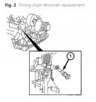
45.Remove timing chain tensioner, Fig. 2.
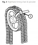
46.Secure timing chain to righthand camshaft sprocket using plastic tie strap, Fig. 3.
47.Remove camshaft sprocket bolts, then camshaft sprockets.
48.Remove camshaft locating plate tool No. 9104 and locking pin tool No. 9105, or equivalents.
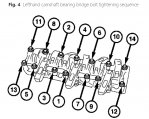
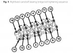
49.Reverse sequences in Figs. 4 and 5, and remove camshaft bearing bridge bolts in two steps.
50.Remove camshaft bearing bridges and camshafts.
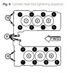
51.Remove cylinder head bolts in sequence, Fig. 6.
52.Remove timing chain tensioner retaining bolt, then tensioner.
53.Remove oil pump drive chain and tensioner.
54.Remove lefthand and righthand camshaft sprocket retaining bolts.
55.Remove timing chain and camshaft sprockets.
56.Remove timing chain crankshaft sprocket.
57.Clean and inspect all gasket surfaces, chain guides and sprockets for wear or damage replace as required.
58.Reverse procedure to install, noting the following:
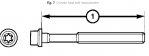
a.Measure and inspect cylinder head bolts prior to reuse. Do not reuse bolts that exceed, 5.66 inch (144 mm) in length, Fig. 7.
b.Tighten cylinder head bolts in four steps using sequence in Fig. 6. Step one, torque head bolts 1-8 to 15 ft. lbs.; step two, torque head bolts 1-8 to 37 ft. lbs.; step three, tighten head bolts 1-8 an additional 60-70°; step four, tighten head bolts 1-8 an additional 60-70°.
c.Torque timing chain cover bolts 15 ft. lbs.
d.Torque camshaft bridge bolts to 11 ft. lbs., then an additional 90° using sequence, Figs. 4 and 5.
e.Torque camshaft sprocket bolts to 37 ft. lbs., then tighten an additional 90°.
f.Ensure crankshaft is at 40° ATDC, Fig. 1.
g.Torque timing chain tensioner bolt to 59 ft. lbs.
h.Torque crankshaft damper bolt to 148 ft. lbs., then tighten an additional 90°.
i.Torque intake manifold bolts to 15 ft. lbs.
j.Torque splash shield bolts to 60 inch lbs.
TIMING CHAIN, REPLACE
1.Relieve fuel pressure as follows:
a.Remove fuel pump relay form power distribution center.
b.Start and run engine until it stalls.
c.Attempt to start engine until it no longer runs.
d.Turn ignition switch to Off position.
e.Place suitable rag or shop towel under fuel line quick-connector fitting at fuel rail.
f.Install fuel pump relay.
g.One or more Diagnostic Trouble Codes (DTCs) may have been stored because of removing fuel pump relay. Clear these DTCs with suitably programmed scan tool.
2.Remove air cleaner assembly housing.
3.Drain engine coolant into suitable container.
4.Remove cooling fan.
5.Remove radiator as follows:
a.Remove air cleaner inlet tubes.
b.Disconnect upper, lower and coolant recovery reservoir hoses.
c.On models equipped with automatic transmission, disconnect transmission fluid cooler lines, then plug openings to prevent leakage and contamination.
d.On all models, remove two radiator hold-down clamps.
e.Tilt radiator forward and remove A/C condenser to radiator retaining bolts.
f.Remove radiator from vehicle.
6.Remove serpentine drive belt.
7.Disconnect mass air flow sensor connector and retaining screws, then remove sensor.
8.Disconnect brake vacuum booster, intake manifold inspect valve and purge vacuum valve hoses.
9.Drain fluid from power steering pump reservoir using suitable fluid removal pump.
10.Disconnect ground lead at power steering pump.
11.Disconnect return and supply lines from power steering pump.
12.Disconnect fuel supply line at fuel rail.
13.Disconnect engine wire harness and connectors.
14.Raise and support vehicle.
15.Remove splash shield retaining bolts, then splash shield.
16.Drain engine oil into suitable container.
17.Remove transmission to rear drive axle propeller shaft.
18.Disconnect transmission wire connectors and wiring harness from retainers at transmission, then position aside.
19.On models equipped with automatic transmission, disconnect gear selector cable from transmission shift lever.
20.On models equipped with manual transmission, disconnect pressure line at clutch slave cylinder, reverse lock-out cable and shift rod from ball stud.
21.On all models, disconnect starter motor connectors and wire harness from starter.
22.Remove front engine mount bolt.
23.Remove lower radiator hose and coolant bypass hose from water pump, then lower vehicle.
24.Remove upper radiator hose from thermostat housing.
25.Remove heater hoses from intake manifold and engine block.
26.Remove A/C compressor bolts, position compressor aside with lines attached.
27.Raise transmission slightly using suitable floor jack.
28.Remove transmission mount and crossmember mounting bolts, then crossmember and transmission mount as an assembly.
29.Attach suitable engine lifting hoist to engine removal eyelets located on engine.
30.Lower rear of transmission with floor jack.
31.Lift engine and transmission as an assembly from vehicle.
32.Separate engine and transmission after mounting onto suitable stand.
33.Separate transmission from engine, then mount engine on suitable engine stand.
34.On models equipped with manual transmission, remove clutch pressure plate, clutch disc and flywheel from engine crankshaft.
35.On models equipped with automatic transmission, remove drive flexplate from engine crankshaft.
36.On all models, remove upper and lower oil pan retaining bolts, then the upper and lower oil pans.
37.Remove power steering pump and idler pulley.
38.Remove mounting bolts and starter.
39.Install flywheel locking tool No. 9102, or equivalent, into starter motor opening.
40.Remove crankshaft damper retaining bolt, then the crankshaft damper.
41.Remove mounting bolts and alternator.
42.Ensure crankshaft is at 40° ATDC, Fig. 1.
43.Disconnect righthand and lefthand exhaust system pipes at exhaust manifolds.
44.Lock camshafts in position using camshaft locating plate tool No. 9104 and locking pin tool No. 9105, or equivalents, place locating plate tool flush on cylinder head and insert locking pin tool into groove located on camshaft.
45.Remove timing chain tensioner, Fig. 2.
46.Secure timing chain to righthand camshaft sprocket using plastic tie strap, Fig. 3.
47.Remove camshaft sprocket bolts, then camshaft sprockets.
48.Remove camshaft locating plate tool No. 9104 and locking pin tool No. 9105, or equivalents.
49.Reverse sequences in Figs. 4 and 5, and remove camshaft bearing bridge bolts in two steps.
50.Remove camshaft bearing bridges and camshafts.
51.Remove cylinder head bolts in sequence, Fig. 6.
52.Remove timing chain tensioner retaining bolt, then tensioner.
53.Remove oil pump drive chain and tensioner.
54.Remove lefthand and righthand camshaft sprocket retaining bolts.
55.Remove timing chain and camshaft sprockets.
56.Remove timing chain crankshaft sprocket.
57.Clean and inspect all gasket surfaces, chain guides and sprockets for wear or damage replace as required.
58.Reverse procedure to install, noting the following:
a.Measure and inspect cylinder head bolts prior to reuse. Do not reuse bolts that exceed, 5.66 inch (144 mm) in length, Fig. 7.
b.Tighten cylinder head bolts in four steps using sequence in Fig. 6. Step one, torque head bolts 1-8 to 15 ft. lbs.; step two, torque head bolts 1-8 to 37 ft. lbs.; step three, tighten head bolts 1-8 an additional 60-70°; step four, tighten head bolts 1-8 an additional 60-70°.
c.Torque timing chain cover bolts 15 ft. lbs.
d.Torque camshaft bridge bolts to 11 ft. lbs., then an additional 90° using sequence, Figs. 4 and 5.
e.Torque camshaft sprocket bolts to 37 ft. lbs., then tighten an additional 90°.
f.Ensure crankshaft is at 40° ATDC, Fig. 1.
g.Torque timing chain tensioner bolt to 59 ft. lbs.
h.Torque crankshaft damper bolt to 148 ft. lbs., then tighten an additional 90°.
i.Torque intake manifold bolts to 15 ft. lbs.
j.Torque splash shield bolts to 60 inch lbs.
Adjuntos
-
 chrysler_crossfire_32_timingchain1.jpg167,8 KB · Visitas: 390
 -
 chrysler_crossfire_32_timingchain2.jpg55,9 KB · Visitas: 346
 -
 chrysler_crossfire_32_timingchain3.jpg81 KB · Visitas: 358
 -
 chrysler_crossfire_32_timingchain4.jpg119,3 KB · Visitas: 358
 -
 chrysler_crossfire_32_timingchain5.jpg102,2 KB · Visitas: 322
 -
 chrysler_crossfire_32_timingchain6.jpg60 KB · Visitas: 385
 -
 chrysler_crossfire_32_timingchain7.jpg48,9 KB · Visitas: 328
Siguenos en:
El contenido de especificaciones técnicas,comentarios, opiniones y otros datos en este foro sólo son con fines informativos y son de exclusiva responsabilidad de cada usuario. Foromecanicos.com no puede y no verifica ni garantiza la exactitud o exhaustividad de la información. Usted utiliza este sitio web bajo su propio riesgo y solo con fines informativos. Las marcas y los logotipos de los fabricantes de automóviles en esta página web son propiedad de los titulares de las mismas.
Usamos cookies.Si continúas utilizando este sitio, estás consintiendo utilizar cookies.