Tobe82
Experto
Trabajando en un Hyundai Accent GL 1.6L 4cil , reemplazando cadena de tiempo, comparto instruciones sirve para modelos 2012-2014
TIMING CHAIN, REPLACE
Caution: With timing chain removed, avoid turning camshaft or crankshaft. If movement is required, exercise extreme caution to avoid valve damage caused by piston contact.
1.Remove engine cover.
2.Relieve fuel system pressure as follows:
a.Turn ignition OFF and disconnect battery ground cable.
b.Remove rear seat cushion.
c.Remove service cover.
d.Disconnect fuel pump connector.
e.Disconnect electrical connector from high pressure fuel pump.
f.Connect battery ground cable.
g.Run engine for about 20 seconds to lower pressure in both high and low pressure lines. Engine may shutoff within 20 second period. If not, turn engine OFF.
h.Proceed with service or repair. Use rags to cover opening and catch spills when opening up high pressure system.
3.Disconnect and isolate battery ground cable.
4.Drain engine coolant into a suitable container.
5.Remove air cleaner assembly.
6.Loosen righthand front wheel lug nuts.
7.Raise and support front of vehicle with jack stands.
8.Remove righthand front wheel and tire assembly.
9.Remove engine under covers.
10.Disconnect A/C compressor switch and alternator electrical connectors.
11.Disconnect cable from alternator B terminal.
12.Disconnect intake oil control valve and exhaust oil control valve electrical connectors.
13.Disconnect ignition coil, injector extension, variable intake system and purge control solenoid valve electrical connectors.
14.Disconnect fuel pressure control valve, intake camshaft position sensor, exhaust camshaft position sensor, front oxygen sensor, rear oxygen sensor and condenser electrical connectors.
15.Disconnect oxygen sensor and condenser electrical connectors.
16.Disconnect fuel and PCV hoses.
17.Remove vacuum pipe assembly.
18.Remove high pressure pipe.
19.Remove high pressure fuel pump and roller tappet.
20.Remove ignition coils.
21.Remove exhaust oil control valve.
22.Remove cylinder head cover with gaskets.
23.Remove exhaust oil control valve adapter.
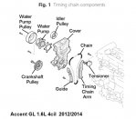
24.Loosen water pump pulley bolt and drive idler mounting bolt, Fig. 1.
25.Loosen alternator tension adjusting bolt to relieve tension.
26.Remove alternator drive belt.
27.Remove alternator.
28.Support engine with a suitable jack.
29.Disconnect ground cable and remove engine mounting support bracket.
30.Remove alternator bracket.
31.Remove engine support bracket.
32.Remove water pump pulley and drive belt idler.
33.Remove water pump.
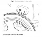
34.Turn crankshaft pulley clockwise, and align its groove with timing mark of timing chain cover, Fig. 2.
35.Remove starter as follows:
a.Disconnect starter cable from B terminal on solenoid, then disconnect connector from S terminal.
b.Remove two starter mounting bolts, then remove starter.
36.Install Hyundai SST tool No. 09231-2B100, or equivalent, to hold ring gear after removing starter.
37.Remove crankshaft bolt and crankshaft pulley.
38.Remove tool holding ring gear.
39.Remove timing chain cover.
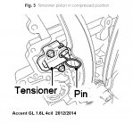
40.Before removing tensioner, fix tensioner piston with a pin through hole at compressed position.
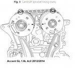
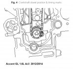
41.Align timing marks of camshaft sprockets with upper surface of cylinder head to make No. 1 cylinder positioned at TDC, Fig. 3. Inspect crankshaft dowel pin for facing upside of engine at this moment, Fig. 4.
42.Remove hydraulic tensioner. Before removing tensioner, fix piston of tensioner with a pin through hole at compressed position, Fig. 5.
43.Remove timing chain tensioner arm and guide.
44.Remove timing chain.
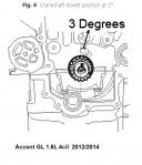
45.Dowel pin of crankshaft should be positioned at 3° in relation to vertical center line, Fig. 6.
46.Align Top Dead Center (TDC) marks of CVVT sprockets with upper surface of cylinder head to make No. 1 cylinder be positioned at TDC, Fig. 7.
47.Install new O-rings.
48.Install timing chain guide and timing chain, Fig. 1. When installing timing chain, align timing marks on sprockets with paint marks of chain. Install timing chain in following order, over crankshaft sprocket, timing chain guide, intake camshaft sprocket, then exhaust camshaft sprocket. Torque timing chain arm attaching bolts to 86-104 inch lbs.
49.Install chain tensioner arm. Torque attaching bolts to 86-104 inch lbs.
50.Install hydraulic tensioner, then remove pin. Torque attaching bolts to 86-104 inch lbs.
51.Install timing chain cover as follows:
a.Apply Hyundai liquid gasket part No. TB 1217H or Loctite part No. 5900H, or equivalent, on surface between cylinder head and cylinder block. Liquid gasket width should be .1181-.1969 inch.
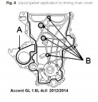
b.Apply Hyundai liquid gasket, Three Bond part No. 1282B or Three Bond part No. 1216E, or equivalent, on water pump contact points of timing chain cover and Hyundai Gray RTV or Three Bond part No. 1217H or Loctite part No. 5900H, or equivalent, on remaining components, Fig. 8. Assemble cover within five minutes.
c.Align dowel pin of cylinder block and holes of oil pump.
d.Torque timing chain cover M8 bolts to 14-17 ft. lbs. Torque M6 bolts to 86-104 inch lbs.
52.Install timing chain cover oil seal using Hyundai SST tool No. 09455-21200, or equivalent.
53.Install Hyundai SST tool No. 09231-2B100, or equivalent, to hold ring gear.
54.Install crankshaft pulley. Torque mounting bolt to 94-101 ft. lbs. When installing pulley, groove on pulley should be positioned outside.
55.Remove tool holding righthand gear and install starting motor. Torque starter motor attaching bolts to 31-40 ft. lbs.
56.Install water pump with gasket. Torque water pump bolts to 86-104 inch lbs.
57.Install water pump pulley. Torque water pump pulley bolts to 86-104 inch lbs.
58.Install drive belt idler. Torque idler bolt to 31-40 ft. lbs.
59.Install engine support bracket. Torque bolts to 22-30 ft. lbs.
60.Install alternator. Torque M8 bolts to 15-20 ft. lbs. Torque M10 bolts to 22-30 ft. lbs.
61.Install accessory drive belt.
62.Install cylinder head cover, note following:
a.Before installing cylinder head cover, remove oil, dust or hardened sealant from timing chain cover and cylinder head upper surface.
b.After applying liquid gasket, Hyundai Gray RTV or Three Bond part No. 1217H or Loctite part No. 5900H, or equivalent, on cylinder head cover, assemble cover within five minutes. Apply a width of .0787-.0984 inch of liquid gasket.
c.Install Oil Control Valve (OCV) adapter. Ensure O-rings on front bearing cap are installed. Torque bolt to 86-104 inch lbs.
d.Install cylinder head cover with a new gasket.
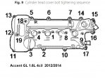
e.Tighten cylinder head cover bolts in two steps using sequence as illustrated in Fig. 9. First step,torque bolt to 36-48 inch lbs., second step, torque bolts to 72-84 inch lbs.
continua....
TIMING CHAIN, REPLACE
Caution: With timing chain removed, avoid turning camshaft or crankshaft. If movement is required, exercise extreme caution to avoid valve damage caused by piston contact.
1.Remove engine cover.
2.Relieve fuel system pressure as follows:
a.Turn ignition OFF and disconnect battery ground cable.
b.Remove rear seat cushion.
c.Remove service cover.
d.Disconnect fuel pump connector.
e.Disconnect electrical connector from high pressure fuel pump.
f.Connect battery ground cable.
g.Run engine for about 20 seconds to lower pressure in both high and low pressure lines. Engine may shutoff within 20 second period. If not, turn engine OFF.
h.Proceed with service or repair. Use rags to cover opening and catch spills when opening up high pressure system.
3.Disconnect and isolate battery ground cable.
4.Drain engine coolant into a suitable container.
5.Remove air cleaner assembly.
6.Loosen righthand front wheel lug nuts.
7.Raise and support front of vehicle with jack stands.
8.Remove righthand front wheel and tire assembly.
9.Remove engine under covers.
10.Disconnect A/C compressor switch and alternator electrical connectors.
11.Disconnect cable from alternator B terminal.
12.Disconnect intake oil control valve and exhaust oil control valve electrical connectors.
13.Disconnect ignition coil, injector extension, variable intake system and purge control solenoid valve electrical connectors.
14.Disconnect fuel pressure control valve, intake camshaft position sensor, exhaust camshaft position sensor, front oxygen sensor, rear oxygen sensor and condenser electrical connectors.
15.Disconnect oxygen sensor and condenser electrical connectors.
16.Disconnect fuel and PCV hoses.
17.Remove vacuum pipe assembly.
18.Remove high pressure pipe.
19.Remove high pressure fuel pump and roller tappet.
20.Remove ignition coils.
21.Remove exhaust oil control valve.
22.Remove cylinder head cover with gaskets.
23.Remove exhaust oil control valve adapter.
24.Loosen water pump pulley bolt and drive idler mounting bolt, Fig. 1.
25.Loosen alternator tension adjusting bolt to relieve tension.
26.Remove alternator drive belt.
27.Remove alternator.
28.Support engine with a suitable jack.
29.Disconnect ground cable and remove engine mounting support bracket.
30.Remove alternator bracket.
31.Remove engine support bracket.
32.Remove water pump pulley and drive belt idler.
33.Remove water pump.
34.Turn crankshaft pulley clockwise, and align its groove with timing mark of timing chain cover, Fig. 2.
35.Remove starter as follows:
a.Disconnect starter cable from B terminal on solenoid, then disconnect connector from S terminal.
b.Remove two starter mounting bolts, then remove starter.
36.Install Hyundai SST tool No. 09231-2B100, or equivalent, to hold ring gear after removing starter.
37.Remove crankshaft bolt and crankshaft pulley.
38.Remove tool holding ring gear.
39.Remove timing chain cover.
40.Before removing tensioner, fix tensioner piston with a pin through hole at compressed position.
41.Align timing marks of camshaft sprockets with upper surface of cylinder head to make No. 1 cylinder positioned at TDC, Fig. 3. Inspect crankshaft dowel pin for facing upside of engine at this moment, Fig. 4.
42.Remove hydraulic tensioner. Before removing tensioner, fix piston of tensioner with a pin through hole at compressed position, Fig. 5.
43.Remove timing chain tensioner arm and guide.
44.Remove timing chain.
45.Dowel pin of crankshaft should be positioned at 3° in relation to vertical center line, Fig. 6.
46.Align Top Dead Center (TDC) marks of CVVT sprockets with upper surface of cylinder head to make No. 1 cylinder be positioned at TDC, Fig. 7.
47.Install new O-rings.
48.Install timing chain guide and timing chain, Fig. 1. When installing timing chain, align timing marks on sprockets with paint marks of chain. Install timing chain in following order, over crankshaft sprocket, timing chain guide, intake camshaft sprocket, then exhaust camshaft sprocket. Torque timing chain arm attaching bolts to 86-104 inch lbs.
49.Install chain tensioner arm. Torque attaching bolts to 86-104 inch lbs.
50.Install hydraulic tensioner, then remove pin. Torque attaching bolts to 86-104 inch lbs.
51.Install timing chain cover as follows:
a.Apply Hyundai liquid gasket part No. TB 1217H or Loctite part No. 5900H, or equivalent, on surface between cylinder head and cylinder block. Liquid gasket width should be .1181-.1969 inch.
b.Apply Hyundai liquid gasket, Three Bond part No. 1282B or Three Bond part No. 1216E, or equivalent, on water pump contact points of timing chain cover and Hyundai Gray RTV or Three Bond part No. 1217H or Loctite part No. 5900H, or equivalent, on remaining components, Fig. 8. Assemble cover within five minutes.
c.Align dowel pin of cylinder block and holes of oil pump.
d.Torque timing chain cover M8 bolts to 14-17 ft. lbs. Torque M6 bolts to 86-104 inch lbs.
52.Install timing chain cover oil seal using Hyundai SST tool No. 09455-21200, or equivalent.
53.Install Hyundai SST tool No. 09231-2B100, or equivalent, to hold ring gear.
54.Install crankshaft pulley. Torque mounting bolt to 94-101 ft. lbs. When installing pulley, groove on pulley should be positioned outside.
55.Remove tool holding righthand gear and install starting motor. Torque starter motor attaching bolts to 31-40 ft. lbs.
56.Install water pump with gasket. Torque water pump bolts to 86-104 inch lbs.
57.Install water pump pulley. Torque water pump pulley bolts to 86-104 inch lbs.
58.Install drive belt idler. Torque idler bolt to 31-40 ft. lbs.
59.Install engine support bracket. Torque bolts to 22-30 ft. lbs.
60.Install alternator. Torque M8 bolts to 15-20 ft. lbs. Torque M10 bolts to 22-30 ft. lbs.
61.Install accessory drive belt.
62.Install cylinder head cover, note following:
a.Before installing cylinder head cover, remove oil, dust or hardened sealant from timing chain cover and cylinder head upper surface.
b.After applying liquid gasket, Hyundai Gray RTV or Three Bond part No. 1217H or Loctite part No. 5900H, or equivalent, on cylinder head cover, assemble cover within five minutes. Apply a width of .0787-.0984 inch of liquid gasket.
c.Install Oil Control Valve (OCV) adapter. Ensure O-rings on front bearing cap are installed. Torque bolt to 86-104 inch lbs.
d.Install cylinder head cover with a new gasket.
e.Tighten cylinder head cover bolts in two steps using sequence as illustrated in Fig. 9. First step,torque bolt to 36-48 inch lbs., second step, torque bolts to 72-84 inch lbs.
continua....
Adjuntos
-
 hyundai-accent-timingchain-1.jpg73,3 KB · Visitas: 491
 -
 hyundai-accent-timingchain-2.jpg78,8 KB · Visitas: 488
 -
 hyundai-accent-timingchain-3.jpg83,3 KB · Visitas: 1.482
 -
 hyundai-accent-timingchain-4.jpg86,4 KB · Visitas: 945
 -
 hyundai-accent-timingchain-5.jpg89,7 KB · Visitas: 472
 -
 hyundai-accent-timingchain-6.jpg79 KB · Visitas: 527
 -
 hyundai-accent-timingchain-7.jpg100,6 KB · Visitas: 995
 -
 hyundai-accent-timingchain-8.jpg80,5 KB · Visitas: 516
 -
 hyundai-accent-timingchain-9.jpg77,5 KB · Visitas: 520