-
Hola Invitado, Foromecanicos es el Foro de Automecanico y Autoelectronico - informacion sobre mecanica automotriz, computers, encendido y auto electronics, diagramas.
Estás utilizando un navegador obsoleto. Este u otros sitios web pueden no ser mostrados correctamente.
Debes actualizarlo o utilizar un navegador alternativo.
Debes actualizarlo o utilizar un navegador alternativo.
Problema Con Motor Ford Explorer 4.6 V8 3v
- Iniciador del tema jublan
- Fecha de inicio
-
- Etiquetas
- ford explorer
ºsaludos a todos,yo estube un problema similar y nadie daba con la solucion.al parecer es un mal de estas camionetas.un especialista en ford me dijo que cambiara el aceite 5w 30 a 15w 40, ya he rodado mas de 20 mil kilometros y se le quito el problema,de todas forma es desicion de cada quien ya que unos dicen que se tapan los ducto y que daña las camaras,ojo es semi sintetico.ojala esta informacion ayude a otros
Buenas noches amigos, soy nuevo en el foro y no se como se crea un nuevo tema, pero necesito ayuda, tengo una ford explorer 4.6 2010, soy de venezuela, la camioneta presenta codigos de fallas que tienen que ver con mal funcionamienfo de algunos cilindros codigos (P0300, P0302, P0304), las posibles causas son problemas con las bobinas de encendido, problemas con las bujias, problemas con los inye tores, lo que causa que el motor tiemble cuando esta en minimo pero no es constante se normaliza por largo toempo y luego buelbe la falla, ya probé desconectando los inyectores uno por uno y al hacerlo el motor tiembla con cada uno loque me indica que los inyectores estan bien, y si la falla fuera constante pudiera pensar que son las bobinas de encendido o las bujias pero la falla no es constante como ya dije , quisiera que me ayuden por favor gracias.
Buenos dias Sres, tengo el mismo problema con mi ford explorer v8 4.6 año 2010, soy de venezuela, el inconveniente comenzo cuando cambie el aceite, siempre utilizaba 10W30 pero por problemas a nivel nacional de abastecimiento, ese aceite es difícil de encontrar, tuve que recurrir al 5W20 que según la tapa, es el remendado por FORD, todo bien hasta los primeros 1000 km, una mañana procedo a encenderla y sono como si fuese un diesel y a los segundos se le quita, desde alli la camioneta parece un poto el ruido al encederla es fuerte, leyendo sus comentarios unos comentan que es la cadena, otros foristas indican que cambiando el aceite a mas grueso, realmente que sera?? si me pueden ayudar se los agradeceria.
Tobe82
Experto
Hola, comparto manual de cambio de cadena de tiempo por si la ocupan
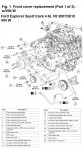
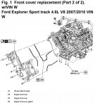
Ford Explorer Sport track 4.6L V8 2007/2010 VIN W
1.Drain cooling system into suitable container.
2.Remove crankshaft front seal.
3.Remove hydraulic roller.
4.Drain engine oil into suitable container.
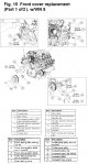
5.Remove components in order listed, Fig. 1.
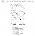
6.Remove front cover bolts in sequence, Fig. 2.
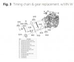
7.Remove timing chain and gears in sequence illustrated, Fig. 3.
8.Reverse procedure to install, noting the following:
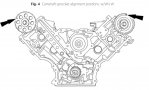
a.Rotate lefthand camshaft timing sprocket until timing mark is approximately at 12 o'clock position. Rotate righthand camshaft sprocket until timing mar is at approximately 11 o'clock position, Fig. 4.
b.Rotate crankshaft counterclockwise only. Do not rotate past position outlined or severe damage to piston and/or valves may occur.
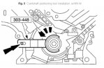
c.Position crankshaft with crankshaft holding tool No. 303-448, or equivalent, Fig. 5.
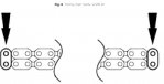
d.If copper marks are not visible, mark one link on one end and one link on other end and use as timing marks, Fig. 6.
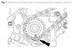
e.Position lefthand (inner) timing chain on crankshaft sprocket, aligning copper link (marked) with timing mark on sprocket, Fig. 7. If required, adjust camshaft sprocket slightly to obtain timing mark alignment.
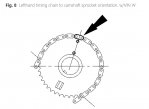
f.Position lefthand timing chain on camshaft sprocket. Ensure copper colored link (marked) aligns with camshaft sprocket timing mark, Fig. 8.
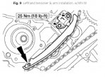
g.Position lefthand timing chain tensioner arm on dowel pin and install lefthand tensioner, Fig. 9.
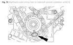
h.Position righthand (outer) timing chain on crankshaft sprocket, aligning copper (marked) link with timing mark on sprocket, Fig. 10. If required, adjust camshaft sprocket slightly to obtain timing mark.
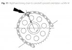
i.Position righthand timing chain on camshaft sprocket. Ensure copper colored link (marked), aligns with camshaft sprocket timing mark, Fig. 11.
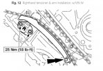
j.Position righthand timing chain tensioner arm on dowel pin and install righthand tensioner, Fig. 12.
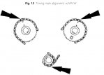
k.Verify correct alignment of all timing marks, Fig. 13.
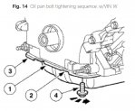
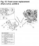
l.Tighten four previously removed oil pan bolts in three steps, using sequence, Fig. 14. First step, torque to 18 inch lbs.; second step, torque to 15 ft. lbs.; third step, tighten all bolts an additional 60° turn.
m.Torque timing chain guide to 89 inch lbs.
Ford Explorer Sport track 4.6L V8 2007/2010 VIN W
1.Drain cooling system into suitable container.
2.Remove crankshaft front seal.
3.Remove hydraulic roller.
4.Drain engine oil into suitable container.
5.Remove components in order listed, Fig. 1.
6.Remove front cover bolts in sequence, Fig. 2.
7.Remove timing chain and gears in sequence illustrated, Fig. 3.
8.Reverse procedure to install, noting the following:
a.Rotate lefthand camshaft timing sprocket until timing mark is approximately at 12 o'clock position. Rotate righthand camshaft sprocket until timing mar is at approximately 11 o'clock position, Fig. 4.
b.Rotate crankshaft counterclockwise only. Do not rotate past position outlined or severe damage to piston and/or valves may occur.
c.Position crankshaft with crankshaft holding tool No. 303-448, or equivalent, Fig. 5.
d.If copper marks are not visible, mark one link on one end and one link on other end and use as timing marks, Fig. 6.
e.Position lefthand (inner) timing chain on crankshaft sprocket, aligning copper link (marked) with timing mark on sprocket, Fig. 7. If required, adjust camshaft sprocket slightly to obtain timing mark alignment.
f.Position lefthand timing chain on camshaft sprocket. Ensure copper colored link (marked) aligns with camshaft sprocket timing mark, Fig. 8.
g.Position lefthand timing chain tensioner arm on dowel pin and install lefthand tensioner, Fig. 9.
h.Position righthand (outer) timing chain on crankshaft sprocket, aligning copper (marked) link with timing mark on sprocket, Fig. 10. If required, adjust camshaft sprocket slightly to obtain timing mark.
i.Position righthand timing chain on camshaft sprocket. Ensure copper colored link (marked), aligns with camshaft sprocket timing mark, Fig. 11.
j.Position righthand timing chain tensioner arm on dowel pin and install righthand tensioner, Fig. 12.
k.Verify correct alignment of all timing marks, Fig. 13.
l.Tighten four previously removed oil pan bolts in three steps, using sequence, Fig. 14. First step, torque to 18 inch lbs.; second step, torque to 15 ft. lbs.; third step, tighten all bolts an additional 60° turn.
m.Torque timing chain guide to 89 inch lbs.
Adjuntos
-
 fordexplorer_sporttrack_46_timingchain_1a.jpg666,3 KB · Visitas: 655
 -
 fordexplorer_sporttrack_46_timingchain_1b.jpg326,8 KB · Visitas: 1.659
 -
 fordexplorer_sporttrack_46_timingchain_2.jpg48 KB · Visitas: 497
 -
 fordexplorer_sporttrack_46_timingchain_3.jpg41,3 KB · Visitas: 484
 -
 fordexplorer_sporttrack_46_timingchain_4.jpg129,5 KB · Visitas: 1.684
 -
 fordexplorer_sporttrack_46_timingchain_5.jpg125,7 KB · Visitas: 531
 -
 fordexplorer_sporttrack_46_timingchain_6.jpg105,7 KB · Visitas: 449
 -
 fordexplorer_sporttrack_46_timingchain_7.jpg132,8 KB · Visitas: 537
 -
 fordexplorer_sporttrack_46_timingchain_8.jpg57,7 KB · Visitas: 456
 -
 fordexplorer_sporttrack_46_timingchain_9.jpg130,3 KB · Visitas: 575
 -
 fordexplorer_sporttrack_46_timingchain_010.jpg141,8 KB · Visitas: 516
Tobe82
Experto
continuacion... Ford Explorer Sport track 4.6L V8 2007/2010 VIN W
Adjuntos
Tobe82
Experto
Ford Explorer Sport track 4.6L V8 2007/2010
VIN 8
1.Raise and support vehicle.
2.Drain engine oil into suitable container.
3.Drain engine coolant into suitable container.
4.Disconnect, then position upper and lower degas bottle hoses aside.
5.Remove two mounting bolts and degas bottle.
6.Rotate accessory drive belt tensioner clockwise with suitable belt tensioner release tool and remove belt.
7.Remove mounting bolt and righthand belt idler pulley.
8.Remove valve covers.
9.Disconnect two coolant hoses from crossover, Fig. 15.
10.Remove mounting nut and position righthand radio ignition interference capacitor aside.
11.Disconnect righthand Camshaft Position (CMP) sensor electrical connector.
12.Remove mounting nut and position lefthand radio ignition interference capacitor aside.
13.Remove J-bracket from engine front cover stud bolt.
14.Disconnect lefthand CMP sensor electrical connector.
15.Remover four mounting bolts and water pump pulley.
16.Remove two mounting nuts and power steering pulley shield.
17.Remove wiring harness, retainer, nut and tube clip from power steering stud bolt.
18.Remove three stud bolts, and support power steering pump aside.
19.Disconnect Crankshaft Position (CKP) sensor connector.
20.Remove crankshaft pulley mounting bolt and washer.
21.Remove crankshaft pulley using suitable three-jaw puller tool.
22.Remove crankshaft seal using crankshaft front seal remover tool No. T74P-66700-A, or equivalent.
23.Remove four front oil pan mounting bolts.
24.Record front cover mounting bolt locations for installation alignment.
25.Remove mounting bolts, studs and front cover.
26.Clean mating surfaces with suitable silicone gasket remover.
27.Remove crankshaft sensor ring.
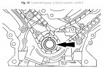
28.Position crankshaft keyway at 12 o'clock position, Fig. 16, noting the following:
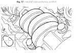
a.If camshaft lobes are not exactly positioned, Fig. 17, crankshaft will require one full additional rotation to 12 o'clock position.
b.Cylinder No. 1 camshaft exhaust lobe must be coming up on exhaust stroke.
c.Ensure positioning of two intake lobes and exhaust lobe on cylinder No. 1.
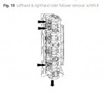
29.Remove three roller followers from lefthand and righthand cylinder heads using valve spring compressor tool No. 303-1039, or equivalent, Fig. 18. Do not allow valve keepers to fall off valve, or valve may drop into cylinder.
30.Rotate crankshaft clockwise and position crankshaft keyway at 6 o'clock position. Do not move crankshaft past 6 o'clock position.
31.Remove mounting bolts, then the lefthand and righthand timing chain tensioners and tensioner arms.
32.Remove righthand timing chain from camshaft and crankshaft sprockets.
33.Remove lefthand timing chain from camshaft and crankshaft sprockets.
34.Remove two mounting bolts and both timing chain guides.
35.Remove mounting bolts, then the lefthand and righthand camshaft phaser sprocket using camshaft phase locking tool No. 303-1046, or equivalent. Caution: Only use hand tools.
36.Mark camshaft bearing caps for installation original locations.
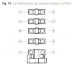
37.Remove camshaft bearing caps bolts in sequence, Fig. 19.
38.Caution: Remove front thrust camshaft bearing cap straight upward from bearing towers. Remove remaining bearing caps.
39.Mark components for installation into original locations.
40.Remove all remaining roller followers.
41.Reverse procedure to install, noting the following:
a.Torque camshaft phaser sprocket bolts using camshaft phase locking tool No. 303-1046, or equivalent, to 30 ft. lbs., then tighten an additional 90° turn.
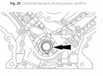
b.Rotate crankshaft to position crankshaft sprocket timing mark in 6 o'clock position, Fig. 20.
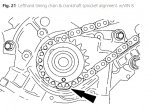
c.Position lower end of lefthand (inner) timing chain on crankshaft sprocket, aligning timing mark on outer flange of crankshaft sprocket with single copper (marked) link on chain, Fig. 21.
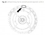
d.Position lefthand timing chain on camshaft sprocket. Ensure camshaft sprocket timing mark is aligned with copper (marked) chain link, Fig. 22.
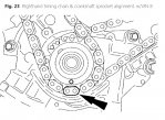
e.Position lower end of righthand (outer) timing chain on crankshaft sprocket, aligning timing mark on sprocket with single copper (marked) chain link, Fig. 23.
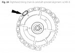
f.Position righthand timing chain on camshaft sprocket. Ensure camshaft sprocket timing mark is aligned with copper (marked) chain link, Fig. 24.
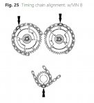
g.Righthand and lefthand camshaft phaser sprockets are similar. Righthand camshaft phaser sprocket has single timing mark to identify, while L timing mark identifies lefthand camshaft phaser sprocket. Ensure timing marks on sprockets align, Fig. 25.
h.Torque timing chain guide to 89 inch lbs.
i.Torque timing chain tensioner to 18 ft. lbs.
j.Torque water pump pulley to 18 ft. lbs.
k.Torque power steering pulley shield to 89 inch lbs.
l.Torque valve covers to 89 inch lbs.
VIN 8
1.Raise and support vehicle.
2.Drain engine oil into suitable container.
3.Drain engine coolant into suitable container.
4.Disconnect, then position upper and lower degas bottle hoses aside.
5.Remove two mounting bolts and degas bottle.
6.Rotate accessory drive belt tensioner clockwise with suitable belt tensioner release tool and remove belt.
7.Remove mounting bolt and righthand belt idler pulley.
8.Remove valve covers.
9.Disconnect two coolant hoses from crossover, Fig. 15.
10.Remove mounting nut and position righthand radio ignition interference capacitor aside.
11.Disconnect righthand Camshaft Position (CMP) sensor electrical connector.
12.Remove mounting nut and position lefthand radio ignition interference capacitor aside.
13.Remove J-bracket from engine front cover stud bolt.
14.Disconnect lefthand CMP sensor electrical connector.
15.Remover four mounting bolts and water pump pulley.
16.Remove two mounting nuts and power steering pulley shield.
17.Remove wiring harness, retainer, nut and tube clip from power steering stud bolt.
18.Remove three stud bolts, and support power steering pump aside.
19.Disconnect Crankshaft Position (CKP) sensor connector.
20.Remove crankshaft pulley mounting bolt and washer.
21.Remove crankshaft pulley using suitable three-jaw puller tool.
22.Remove crankshaft seal using crankshaft front seal remover tool No. T74P-66700-A, or equivalent.
23.Remove four front oil pan mounting bolts.
24.Record front cover mounting bolt locations for installation alignment.
25.Remove mounting bolts, studs and front cover.
26.Clean mating surfaces with suitable silicone gasket remover.
27.Remove crankshaft sensor ring.
28.Position crankshaft keyway at 12 o'clock position, Fig. 16, noting the following:
a.If camshaft lobes are not exactly positioned, Fig. 17, crankshaft will require one full additional rotation to 12 o'clock position.
b.Cylinder No. 1 camshaft exhaust lobe must be coming up on exhaust stroke.
c.Ensure positioning of two intake lobes and exhaust lobe on cylinder No. 1.
29.Remove three roller followers from lefthand and righthand cylinder heads using valve spring compressor tool No. 303-1039, or equivalent, Fig. 18. Do not allow valve keepers to fall off valve, or valve may drop into cylinder.
30.Rotate crankshaft clockwise and position crankshaft keyway at 6 o'clock position. Do not move crankshaft past 6 o'clock position.
31.Remove mounting bolts, then the lefthand and righthand timing chain tensioners and tensioner arms.
32.Remove righthand timing chain from camshaft and crankshaft sprockets.
33.Remove lefthand timing chain from camshaft and crankshaft sprockets.
34.Remove two mounting bolts and both timing chain guides.
35.Remove mounting bolts, then the lefthand and righthand camshaft phaser sprocket using camshaft phase locking tool No. 303-1046, or equivalent. Caution: Only use hand tools.
36.Mark camshaft bearing caps for installation original locations.
37.Remove camshaft bearing caps bolts in sequence, Fig. 19.
38.Caution: Remove front thrust camshaft bearing cap straight upward from bearing towers. Remove remaining bearing caps.
39.Mark components for installation into original locations.
40.Remove all remaining roller followers.
41.Reverse procedure to install, noting the following:
a.Torque camshaft phaser sprocket bolts using camshaft phase locking tool No. 303-1046, or equivalent, to 30 ft. lbs., then tighten an additional 90° turn.
b.Rotate crankshaft to position crankshaft sprocket timing mark in 6 o'clock position, Fig. 20.
c.Position lower end of lefthand (inner) timing chain on crankshaft sprocket, aligning timing mark on outer flange of crankshaft sprocket with single copper (marked) link on chain, Fig. 21.
d.Position lefthand timing chain on camshaft sprocket. Ensure camshaft sprocket timing mark is aligned with copper (marked) chain link, Fig. 22.
e.Position lower end of righthand (outer) timing chain on crankshaft sprocket, aligning timing mark on sprocket with single copper (marked) chain link, Fig. 23.
f.Position righthand timing chain on camshaft sprocket. Ensure camshaft sprocket timing mark is aligned with copper (marked) chain link, Fig. 24.
g.Righthand and lefthand camshaft phaser sprockets are similar. Righthand camshaft phaser sprocket has single timing mark to identify, while L timing mark identifies lefthand camshaft phaser sprocket. Ensure timing marks on sprockets align, Fig. 25.
h.Torque timing chain guide to 89 inch lbs.
i.Torque timing chain tensioner to 18 ft. lbs.
j.Torque water pump pulley to 18 ft. lbs.
k.Torque power steering pulley shield to 89 inch lbs.
l.Torque valve covers to 89 inch lbs.
Adjuntos
-
 fordexplorer_sporttrack_46_timingchain_015a.jpg460,6 KB · Visitas: 526
 -
 fordexplorer_sporttrack_46_timingchain_015b.jpg255,3 KB · Visitas: 558
 -
 fordexplorer_sporttrack_46_timingchain_016.jpg177,2 KB · Visitas: 1.670
 -
 fordexplorer_sporttrack_46_timingchain_017.jpg137,1 KB · Visitas: 400
 -
 fordexplorer_sporttrack_46_timingchain_018.jpg52,5 KB · Visitas: 403
 -
 fordexplorer_sporttrack_46_timingchain_019.jpg47,3 KB · Visitas: 422
 -
 fordexplorer_sporttrack_46_timingchain_020.jpg68,2 KB · Visitas: 476
 -
 fordexplorer_sporttrack_46_timingchain_021.jpg145,8 KB · Visitas: 972
 -
 fordexplorer_sporttrack_46_timingchain_022.jpg81,8 KB · Visitas: 414
 -
 fordexplorer_sporttrack_46_timingchain_023.jpg159,3 KB · Visitas: 429
 -
 fordexplorer_sporttrack_46_timingchain_024.jpg82,4 KB · Visitas: 481
 -
 fordexplorer_sporttrack_46_timingchain_025.jpg46,4 KB · Visitas: 1.072
Ramiro Barillas
Nuevo Miembro
Buenos dias tengo una explorer año 2010 motor 4.6 3V. el motor fue reparado hace seis meses por un problema de lubricación que presento y desde el momento de la reparación el motor suena como un motor Diesel. un mecanico le desconecto las valvulas VVT y dejo de sonar, solo suena al momento de encenderlo en la mañana o en cualquier momento del día y al ponerlo en marcha deja de sonar.
lo que he notado es que en subidas tiene poca potencia debe ser por la desconexión de las valvulas VVT
el mecanico me ha sugerido bloquear las valvulas VVT para que el motor mejore su rendimiento.
quisiera saber su comentario respecto a la recomendación del mecanico de bloquear las valvula VVT.
y si por estar desconectadas las valvulas en este momento el motor pudiera sufrir un daño mayor.
Saludos
Ramiro Barillas desde Venezuela.
Siguenos en:
El contenido de especificaciones técnicas,comentarios, opiniones y otros datos en este foro sólo son con fines informativos y son de exclusiva responsabilidad de cada usuario. Foromecanicos.com no puede y no verifica ni garantiza la exactitud o exhaustividad de la información. Usted utiliza este sitio web bajo su propio riesgo y solo con fines informativos. Las marcas y los logotipos de los fabricantes de automóviles en esta página web son propiedad de los titulares de las mismas.
Usamos cookies.Si continúas utilizando este sitio, estás consintiendo utilizar cookies.