Pra quien ocupe reemplazar cadena de tiempo Dodge Charger 2.7L v6 2006/2010
TIMING CHAIN, REPLACE
1.Drain cooling system into suitable container.
2.Relieve fuel system pressure as follows:
a.Remove fuel fill cap.
b.Disconnect fuel pump module electrical connector.
c.Start and run engine until it stalls.
d.Attempt restarting engine until it will no longer run.
e.Turn ignition key to Off position.
f.Place a rag or towel below fuel line quick-connect fitting at fuel rail.
g.Disconnect quick-connect fitting at fuel rail.
h.Erase any DTCs that may have been stored in Powertrain Control Module (PCM) memory due to disconnecting fuel pump module circuit.
3.Raise and support vehicle on hoist.
4.Rotate belt tensioner counterclockwise until it contacts stop.
5.Remove belt and slowly rotate tensioner into freearm position. Do not let tensioner arm snap back to freearm position.
6.Hold damper using damper holder tool No. 9365, or equivalent, then remove damper mounting bolts.
7.Remove damper using suitable three-jaw puller.
8.Disconnect Camshaft Position (CMP) and coolant temperature sensors' connectors.
9.Remove upper and lower intake manifolds.
10.Remove cylinder head covers.
11.Remove mounting bolts and radiator.
12.Remove radiator upper hose at tube.
13.Remove heater hose from heater tube at rear of engine.
14.Disconnect heater tube from retaining clip at rear of engine.
15.Remove mounting screws, then disconnect and remove heater tube from outlet connector.
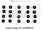
16.Remove camshaft bearing caps gradually in sequence, Fig. 1.
17.Mark position for install alignment, then remove camshafts and valve train components from cylinder head.
18.On lefthand cylinder head, proceed as follows:
a.Remove oil dipstick tube to cylinder head mounting bolt.
b.Remove engine oil dipstick tube.
c.Remove alternator.
19.On righthand cylinder head, proceed as follows:
a.Remove cylinder head ground strap.
b.Disconnect electrical connector and remove EGR valve from head.
20.On all models, ensure cylinder head bolts No. 1-3 are removed before attempting removal of cylinder head.
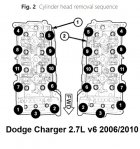
21.Remove cylinder head bolts in sequence, Fig. 2.
22.Remove mounting bolts and lower splash shield.
23.Hold damper using damper holder tool No. 9365, or equivalent, then remove damper mounting bolts.
24.Remove damper using suitable three-jaw puller.
25.Lower vehicle.
26.Remove mounting bolts and timing chain cover. Discard timing chain cover gasket.
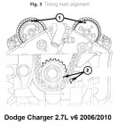
27.Rotate crankshaft until crankshaft sprocket timing mark aligns with timing mark on oil pump housing, Fig. 3. Mark on oil pump housing is 60° ATDC of cylinder No. 1.
28.Remove cap and primary timing chain tensioner retainer cap from righthand cylinder head.
29.Disconnect and remove Camshaft Position (CMP) sensor from lefthand cylinder head.
30.Remove timing chain guide access plugs from cylinder heads.
31.Remove mounting bolts, righthand camshaft damper and sprocket. When camshaft sprocket bolts are removed, camshafts rotate in clockwise direction.
32.Remove mounting bolts and lefthand camshaft sprocket.
33.Reverse procedure to install, note following:
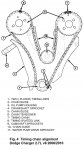
a.Align crankshaft sprocket timing to oil pump housing marks, Fig. 4.
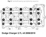
b.Tighten camshaft bearing caps in sequence, Fig. 5.
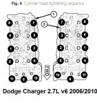
c.Tighten cylinder head in sequence, Fig. 6, bolt Nos. 1-8 in four steps: First step, torque bolts to 35 ft. lbs.; second step, torque bolts to 55 ft. lbs.; third step, torque bolts to 55 ft. lbs.; fourth step, tighten bolts an additional 90°.
d.Tighten cylinder head in sequence, Fig. 6, bolt Nos. 9-11 in two steps: First step, torque bolts to 21 ft. lbs.; second step, torque bolts to 21 ft. lbs.
e.Torque belt tensioner to 40 ft. lbs.
f.Torque camshaft sprocket to 20 ft. lbs.
g.Torque crankshaft damper to 125 ft. lbs.
h.Torque idler pulley to 20 ft. lbs.
i.Torque radiator to support bracket to 105 inch lbs.
j.Torque timing chain guide access plug to 15 ft. lbs.
k.Torque timing chain tensioner to 105 inch lbs.
l.Torque upper radiator closure panel to 90 inch lbs.
m.Torque intake manifold to 105 inch lbs.