buenas tarde quiero saber si tendra un diagrama o guia para poner a tiempo un motor volvo 6 cilindros en linea turbo 2.9 es de una camioneta modelo xc 90 año 2005
Comparto para cambiar la banda de tiempo en un Volvo XC 90 T6 2005 2.9L B6294T
Años 2000-05
These engines are classified as an Interference engine. If the timing belt breaks or jumps timing, a piston may contact an open valve. Piston to valve contact may cause damage to the valve, piston and other engine components. In some cases valve to valve contact may be experienced when the timing belt breaks or jumps timing. To avoid belt breakage, replace the timing belt as recommended by the vehicle manufacturer timing belt replacement interval.
With the timing belt removed, avoid turning the camshaft or crankshaft. If movement is required, exercise extreme caution to avoid valve damage caused by piston contact.
1.Disconnect and isolate the battery ground cable.
2.Remove the screw securing the engine stabilizer brace to the engine bracket.
3.Remove the screws attaching the engine stabilizer brace to the strut towers, then the brace.
4.On turbocharged engines, proceed as follows:
a.Remove the plastic pipes between the turbocharger and charge air cooler and the air cleaner and turbocharger and position aside.
b.Remove the clamp for the intake manifold at the turbocharger for cylinders 1, 2 and 3. Position upper section of the pipe toward the fire wall.
5.On all engines, remove the accessory drive belt.
6.Remove the upper timing belt cover, then the front timing belt cover.
7.Lift the servo reservoir and position on top of engine. Ensure oil does not leak from the filler cap.
8.Clamp the expansion tank to radiator hose. Disconnect the expansion tank and hose and position the expansion tank aside.
9.Loosen the right front wheel lugnuts.
10.Raise and support the front of the vehicle with jackstands, then remove the right wheel and tire assembly.
11.Remove the fender liner retaining nuts, then the liner.
12.Install the upper timing belt cover.
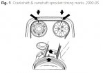
13.Turn the crankshaft clockwise until the crankshaft and camshaft timing marks are aligned, Fig. 1.
14.Rotate the crankshaft an additional 1/4 turn clockwise.
15.Turn the crankshaft back counterclockwise until crankshaft and camshaft sprocket timing marks align, Fig. 1.
16.Remove the upper timing belt cover.
17.Hold the crankshaft center nut in position, remove the four crankshaft pulley attaching bolts, then the pulley.
18.Remove the belt cover located behind the crankshaft pulley.
19.Loosen the timing belt tensioner center screw slightly.
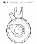
20.While holding the tensioner center screw, turn the tensioner eccentric counterclockwise with a 6 mm hex wrench to the 10 o'clock position, Fig. 2.
21.Remove the timing belt.
22.Ensure the crankshaft sprocket and camshaft sprocket timing marks are properly aligned, Fig. 1.
23.Install the timing belt around the crankshaft sprocket, idler pulley, intake camshaft sprocket, exhaust camshaft sprocket, water pump sprocket and the tensioner pulley. On engines with variable valve timing, use care when installing the timing belt that the variable valve timing unit does not become dislodged.
24.Carefully turn the crankshaft clockwise until the timing belt is tensioned between the intake camshaft sprocket, idler pulley and the crankshaft sprocket. The timing belt should be tensioned with the engine cold.
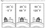
25.While holding the timing belt tensioner center screw in position, rotate the tensioner eccentric clockwise with a 6 mm hex wrench until the tension indicator passes the marked position, Fig. 3.
26.Turn the timing belt tensioner eccentric back so that the tension indicator reaches the marked position in the center of the window.
27.While holding the timing belt tensioner eccentric in position, torque the tensioner center screw to 15 ft. lbs.
28.Ensure the tensioner indicator is in the correct position, Fig. 3.
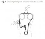
29.Press on the timing belt, Fig. 4, and inspect that indicator on the timing belt tensioner moves easily.
30.Install the upper timing belt cover.
31.Turn the crankshaft two revolutions in the clockwise direction, aligning the crankshaft and camshaft sprocket timing marks. If the timing marks are not aligned, the timing belt must be removed and installed.
32.Ensure the tensioner indicator is in the correct position, Fig. 3.
33.Install the cover located behind crankshaft pulley.
34.Install the crankshaft pulley. Torque the attaching bolts to 26 ft. lbs., then turn each bolt an additional 50°. Use a suitable tool on the crankshaft center nut to hold the pulley in position when tightening the attaching bolts.
35.Install the fender liner and secure with the attaching nuts.
36.Install the right front wheel and tire assembly.
37.Remove the jack stand and lower the vehicle.
38.Tighten the right front wheel and tire assembly lugnuts to 87 ft. lbs.
39.Perform steps 1 through 8 in reverse order to complete installation.
")