Tobe82
Experto
Cambiando cadena de tiempo para un Envoy GMC 2006 5.3L V8
Sirve para GMC Envoy 2003/2009
TIMING CHAIN & GEAR SET, REPLACE
Caution: With the timing chain removed, avoid turning the camshaft or crankshaft. If movement is required, exercise extreme caution to avoid valve damage caused by piston contact.
1.Disconnect and isolate battery ground cable.
2.Drain engine coolant into suitable container.
3.Remove accessory drive belt.
4.Remove water pump as follows:
a.Loosen throttle body Mass Air Flow/Intake Air Temperature (MAF/IAT) sensor air cleaner outlet duct clamps, then remove air cleaner outlet duct.
b.remove engine sight shield.
c.remove radiator vent inlet hose from clips.
d.Remove water pump inlet hose.
e.Remove upper fan shroud.
f.Remove fan using fan clutch remover and installer GM tool No. J-41240 or equivalent.
g.Remove water pump outlet, surge tank outlet hose and heater inlet hoses.
h.Remove mounting bolts and water pump pulley.
i.Remove mounting bolts, water pump and gaskets. Discard gaskets.
5.Remove crankshaft balancer as follows:
a.Remove starter motor.
b.Install flywheel holder GM tool No. J-42386-A or equivalent.
c.Remove crankshaft damper bolt.
d.Remove crankshaft damper using puller tool Nos. J-41816 and J-41816-2, or equivalents.
6.Remove oil pan to front cover mounting bolts.
7.Remove mounting bolts, front cover and gasket. Discard gasket.
8.Remove oil pump as follows:
a.Remove mounting bolt, nuts and oil pump screen with O-ring seal. Discard seal.
b.Remove mounting nuts and crankshaft oil deflector.
c.Remove mounting bolts and oil pump.
9.Rotate crankshaft until timing marks on crankshaft and camshaft sprockets are aligned.
10.Remove mounting bolts, camshaft sprocket and timing chain.
11.Remove crankshaft sprocket using crankshaft sprocket puller tool Nos. J-41558, J-41816-2 and J-8433-1, or equivalents.
12.Remove crankshaft key.
13.Install key into keyway, if required.
14.Install crankshaft sprocket onto front of crankshaft. Align crankshaft key with crankshaft sprocket keyway.
15.Install sprocket onto crankshaft until fully seated against crankshaft flange using sprocket installer GM tool No. J-41665 or equivalent.
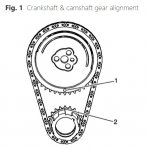
16.Rotate crankshaft sprocket until alignment mark is in 12 o'clock position, Fig. 1.
17.Install camshaft sprocket and timing chain.
18.Align camshaft sprocket locating pin with camshaft sprocket alignment hole.
19.Position camshaft sprocket alignment mark in 6 o'clock position.
20.Rotate camshaft or crankshaft sprockets to align timing marks.
21.Install camshaft sprocket mounting bolts. Torque mounting bolts to 26 ft. lbs.
22.Install oil pump. Torque oil pump and oil pump screen fasteners to 18 ft. lbs.
23.Apply .20 inch bead of sealant No. 12378190 or equivalent .80 inch long to oil pan to engine block junction.
24.Install new gasket and front cover.
25.Install mounting bolts until snug. Caution: Do not overtighten.
26.Install oil pan to front cover bolts until snug. Caution: Do not over tighten.
27.Install front and rear cover alignment GM tool No. J-41476, or equivalent, to front cover. Align tapered legs with machined alignment surfaces on front cover.
28.Install crankshaft balancer bolt until snug. Caution: Do not over tighten.
29.Tighten oil pan to front cover and front cover mounting bolts.
30.Remove alignment tool.
31.Install new crankshaft front oil seal.
32.Install water pump.
33.Install damper using crankshaft damper installation GM tool No. J-41665 or equivalent.
34.Remove damper installation tool and install crankshaft damper bolt.
35.Remove crankshaft damper bolt and measure for correctly installed damper. Nose of crankshaft should be recessed .094-.176 inch into damper bore.
36.If damper is not installed properly, repeat installation procedure.
37.install new crankshaft damper bolt and torque to 37 ft. lbs., then tighten bolt an additional 140° turn.
38.Remove flywheel holder tool.
39.Install accessory drive belt.
40.Inspect cooling system and fill to proper level with recommended coolant, as required.
41.Fill engine crankcase to proper level with recommended engine oil.
42.Connect battery ground cable.
43.Start engine and confirm proper operation, and ensure there are no leaks.
44.Clear DTC(s) using a suitably programmed scan tool.
Sirve para GMC Envoy 2003/2009
TIMING CHAIN & GEAR SET, REPLACE
Caution: With the timing chain removed, avoid turning the camshaft or crankshaft. If movement is required, exercise extreme caution to avoid valve damage caused by piston contact.
1.Disconnect and isolate battery ground cable.
2.Drain engine coolant into suitable container.
3.Remove accessory drive belt.
4.Remove water pump as follows:
a.Loosen throttle body Mass Air Flow/Intake Air Temperature (MAF/IAT) sensor air cleaner outlet duct clamps, then remove air cleaner outlet duct.
b.remove engine sight shield.
c.remove radiator vent inlet hose from clips.
d.Remove water pump inlet hose.
e.Remove upper fan shroud.
f.Remove fan using fan clutch remover and installer GM tool No. J-41240 or equivalent.
g.Remove water pump outlet, surge tank outlet hose and heater inlet hoses.
h.Remove mounting bolts and water pump pulley.
i.Remove mounting bolts, water pump and gaskets. Discard gaskets.
5.Remove crankshaft balancer as follows:
a.Remove starter motor.
b.Install flywheel holder GM tool No. J-42386-A or equivalent.
c.Remove crankshaft damper bolt.
d.Remove crankshaft damper using puller tool Nos. J-41816 and J-41816-2, or equivalents.
6.Remove oil pan to front cover mounting bolts.
7.Remove mounting bolts, front cover and gasket. Discard gasket.
8.Remove oil pump as follows:
a.Remove mounting bolt, nuts and oil pump screen with O-ring seal. Discard seal.
b.Remove mounting nuts and crankshaft oil deflector.
c.Remove mounting bolts and oil pump.
9.Rotate crankshaft until timing marks on crankshaft and camshaft sprockets are aligned.
10.Remove mounting bolts, camshaft sprocket and timing chain.
11.Remove crankshaft sprocket using crankshaft sprocket puller tool Nos. J-41558, J-41816-2 and J-8433-1, or equivalents.
12.Remove crankshaft key.
13.Install key into keyway, if required.
14.Install crankshaft sprocket onto front of crankshaft. Align crankshaft key with crankshaft sprocket keyway.
15.Install sprocket onto crankshaft until fully seated against crankshaft flange using sprocket installer GM tool No. J-41665 or equivalent.
16.Rotate crankshaft sprocket until alignment mark is in 12 o'clock position, Fig. 1.
17.Install camshaft sprocket and timing chain.
18.Align camshaft sprocket locating pin with camshaft sprocket alignment hole.
19.Position camshaft sprocket alignment mark in 6 o'clock position.
20.Rotate camshaft or crankshaft sprockets to align timing marks.
21.Install camshaft sprocket mounting bolts. Torque mounting bolts to 26 ft. lbs.
22.Install oil pump. Torque oil pump and oil pump screen fasteners to 18 ft. lbs.
23.Apply .20 inch bead of sealant No. 12378190 or equivalent .80 inch long to oil pan to engine block junction.
24.Install new gasket and front cover.
25.Install mounting bolts until snug. Caution: Do not overtighten.
26.Install oil pan to front cover bolts until snug. Caution: Do not over tighten.
27.Install front and rear cover alignment GM tool No. J-41476, or equivalent, to front cover. Align tapered legs with machined alignment surfaces on front cover.
28.Install crankshaft balancer bolt until snug. Caution: Do not over tighten.
29.Tighten oil pan to front cover and front cover mounting bolts.
30.Remove alignment tool.
31.Install new crankshaft front oil seal.
32.Install water pump.
33.Install damper using crankshaft damper installation GM tool No. J-41665 or equivalent.
34.Remove damper installation tool and install crankshaft damper bolt.
35.Remove crankshaft damper bolt and measure for correctly installed damper. Nose of crankshaft should be recessed .094-.176 inch into damper bore.
36.If damper is not installed properly, repeat installation procedure.
37.install new crankshaft damper bolt and torque to 37 ft. lbs., then tighten bolt an additional 140° turn.
38.Remove flywheel holder tool.
39.Install accessory drive belt.
40.Inspect cooling system and fill to proper level with recommended coolant, as required.
41.Fill engine crankcase to proper level with recommended engine oil.
42.Connect battery ground cable.
43.Start engine and confirm proper operation, and ensure there are no leaks.
44.Clear DTC(s) using a suitably programmed scan tool.