Mas informacion de apoyo , Cadena de Tiempo Infiniti M45 4.5L V8 VK45DE 2003/ 2010
TIMING CHAIN & GEAR SET, REPLACE
Caution: With timing chain removed, avoid turning camshaft or crankshaft. If movement is required, exercise extreme caution to avoid valve damage caused by piston contact.
1.Relieve fuel system pressure as follows:
a.Remove fuel pump relay and start engine.
b.After engine stalls, crank engine two or three times to release fuel pressure.
c.Turn ignition switch Off and connect fuel pump relay.
2.Disconnect and isolate battery ground cable.
3.Remove engine compartment and engine under covers.
4.Drain engine coolant into suitable container.
5.Drain engine oil into suitable container.
6.Remove hood, front tower bar, battery and air duct inlet.
7.Remove air duct, air cleaner case and drive belts.
8.Remove power valve vacuum tank.
9.Remove cooling fan and tubes.
10.Remove radiator.
11.Remove water suction pipe.
12.Disconnect engine compartment electrical harness and position aside.
13.Disconnect heater hoses. Plug or cap lines and openings.
14.Disconnect exhaust manifold cover wire bonding.
15.Disconnect vacuum hoses and position aside.
16.Remove cooling fan reservoir tank.
17.Remove mounting bolts and air conditioning compressor from bracket.
18.Position compressor aside and suspend with suitable wire.
19.Disconnect fuel line connectors.
20.Disconnect power steering reservoir tank and position aside.
21.Position relay case aside.
22.Remove mounting bolts and position power steering pump aside.
23.Remove automatic transmission oil cooler pipe.
24.Remove front exhaust pipes.
25.Disconnect power steering gear lower joint and release shaft.
26.Remove driveshaft. Before removing propeller shaft, place matching marks on propeller shaft yoke and companion flange to ensure proper alignment during installation.
27.Remove automatic transaxle as follows:
a.Remove control rod.
b.Disconnect rear propeller shaft from transmission.
c.Remove rack stay.
d.Remove starter motor.
e.Remove rear plate cover.
f.Turn crankshaft and remove torque converter mounting bolts.
g.Remove automatic transmission fluid cooler tubes.
h.Plug up openings such as automatic transmission fluid cooler tube holes.
i.Support transmission assembly with a suitable transmission jack.
j.Remove rear engine mounting member and engine mounting rear insulator.
k.Disconnect automatic transmission assembly connector.
l.Remove harness and harness brackets.
m.Remove bolts attaching transmission assembly to engine.
n.Remove air breather hose, air breather box and bracket.
o.Remove transmission from vehicle.
28.Install engine slings to cylinder heads, and support engine with suitable hoist. When turning crankshaft, turn it clockwise as viewed from front of engine.
29.Remove engine mount nuts.
30.Lift and move engine upward.
31.Remove exhaust manifold rear end.
32.Remove engine.
33.Remove mounting bolts, auto-tensioners and idler pulley.
34.Remove water inlet and thermostat.
35.Remove engine oil pan and strainer.
36.Remove mounting bolts and ignition coils.
37.Remove valve cover attaching bolts, then covers.
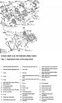
38.Remove mounting bolts, intake valve timing control position and camshaft position sensors, Fig. 1.
39.Remove mounting bolts and intake valve timing control solenoid valve.
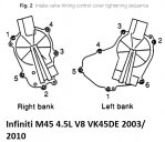
40.Remove intake valve timing control cover mounting bolts in reverse of tightening sequence, Fig. 2.
41.Remove intake valve timing control cover using suitable seal cutter.
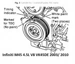
42.Set cylinder No. 1 at compression stroke TDC. Align unpainted crankshaft pulley TDC identification notch with timing indicator, Fig. 3.
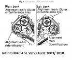
43.Ensure camshaft sprocket mating marks are properly position, Fig. 4. If not, turn engine 360 degrees.
44.Lock crankshaft with hammer handle, or other suitable tool, and loosen crankshaft pulley mounting bolt. Caution: Do not remove mounting bolt.
45.Remove crankshaft pulley using both hands. Keep loosening mounting bolt and moving pulley. Caution: Do not remove inner hexagon bolt balance weight.
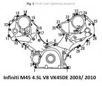
46.Remove front cover mounting bolts in reverse of tightening sequence, Fig. 5.
47.Remove front cover using suitable seal cutter.
48.Reverse procedure to install, noting the following:
a.Apply .12 inch diameter bead of suitable sealant to front cover sealing surface.
b.Ensure camshaft sprocket mating marks are properly position, Fig. 4.
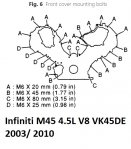
c.Install proper length mounting bolts, Fig. 6.
d.Torque front cover mounting bolts to 10 ft. lbs. in sequence, Fig. 5.
e.Install three new seal rings in intake valve timing control cover.
f.Apply .102-.142 inch diameter bead of suitable sealant to intake valve timing control covers sealing surfaces.
g.Torque intake valve timing control cover mounting bolts to 10 ft. lbs. in sequence, Fig. 2.
h.Apply suitable engine oil to crankshaft pulley mounting bolt threads and seating area.
i.Tighten crankshaft pulley mounting bolt in two steps. First step, torque bolt to 72 ft. lbs.; second step, tighten bolt an additional 90° turn.
j.Install accessory drive belt.
k.Fill cooling system to proper level with recommended coolant.
l.Fill engine crankcase to proper level with recommended engine oil.
m.Install fuel pump fuse/relay and start engine.
n.Connect battery ground cable.
o.Evacuate and charge air conditioning refrigerant system using suitable charging/recovery equipment.
p.Start engine and confirm proper operation, and ensure there are no leaks.
q.With a suitably programmed scan tool, clear DTC(s).