Hola, dejo manual de cadena de tiempo para Nisssan Versa 1.8 2007/2012
TIMING CHAIN, REPLACE
Caution: With timing chain removed, avoid turning camshaft or crankshaft. If movement is required, exercise extreme caution to avoid valve damage caused by piston contact.
1.Relieve fuel system pressure as follows:
a.Remove fuel pump fuse from fuse panel.
b.Start and run engine until it stalls.
c.After engine stalls, crank starter two or three times to ensure fuel pressure is fully relieved.
d.Turn ignition Off and install fuse for fuel pump.
2.Drain engine oil into a suitable container.
3.Drain coolant into a suitable container.
4.Raise and support front of vehicle with jack stands.
5.Remove righthand front wheel.
6.Remove righthand front fender protector.
7.Remove valve cover as follows:
a.Remove ignition coil mounting bolts, then ignition coils.
b.Remove spark plugs.
c.Remove bolts in reverse sequence as outlined, Fig. 1
8.Remove accessory drive belt.
9.Remove water pump pulley.
10.Remove ground cable between righthand engine bracket and radiator core support.
11.Support bottom surface of engine using a transmission jack, and then remove righthand engine bracket and insulator.
12.Set No. 1 cylinder at TDC on its compression stroke, Fig. 2.
13.Rotate crankshaft pulley clockwise and align TDC mark.
14.Ensure that cam noses of No. 1 cylinder are located as outlined, Fig. 3.
15.If not, rotate crankshaft pulley 360°.
16.Remove lower oil pan as follows:
a.Remove oil filter.
b.Remove lower oil pan bolts in reverse sequence, Fig. 4
c.Remove lower oil pan.
17.Remove intake valve timing control solenoid valve.
18.Remove drive belt auto-tensioner.
19.Remove front cover mounting bolts in reverse sequence, Fig. 5
20.Remove front cover.
21.Remove front oil seal from front cover.
22.Push in timing chain tensioner plunger.
23.Insert a stopper pin into body hole to retain plunger in collapsed position, Fig. 6.
24.Remove timing chain tensioner.
25.Remove timing chain slack guide, timing chain tension guide and timing chain.
26.Press stopper tab to push timing chain slack guide toward timing chain tensioner.
27.Insert stopper pin into tensioner body hole to secure timing chain slack guide, Fig. 7.
28.Remove oil pump timing chain tensioner.
29.Remove crankshaft sprocket, oil pump sprocket and oil pump drive chain as a set.
30.Remove timing chain tension guide from front cover.
31.Install timing chain.
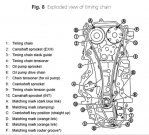
32.Ensure that crankshaft key points are aligned, Fig. 8
33.Install timing chain tension guide to front cover.
34.Install oil pump.
35.Install oil pump drive chain and tensioner.
36.Remove stopper pin after installing chain tensioner.
37.Align matching marks of each sprocket with matching marks of timing chain, Figs. 8 and 9.
38.Install timing chain tension guide and timing chain slack guide.
39.Install timing chain tensioner and pull out stopper pin.
40.Inspect matching mark position of timing chain and each sprocket again.
41.Install front oil seal.
42.Install new O-ring to cylinder block.
43.Install front cover, and tighten bolts in sequence, Figs. 5 and 10.
a.Torque M6 bolt to 58 inch lbs.
b.Torque M10 bolts to 41 ft. lbs.
c.Torque M12 bolts to 55 ft. lbs.
d.Torque M8 bolts to 19 ft. lbs.
44.Install crankshaft pulley and tighten bolt in two steps: First step, torque bolt to 22 ft. lbs.; second step, rotate bolt 60°.
45.Ensure that crankshaft rotates clockwise smoothly.
46.Install lower oil pan and gasket. Torque lower oil pan mounting bolts to 89 inch lbs. in sequence, Fig. 4.
47.Install ground cable between righthand engine bracket and radiator core support.
48.Install water pump pulley.
49.Install valve cover as follows:
a.Install valve cover gasket to valve cover.
b.In sequence, Fig. 1, tighten valve cover bolts in two steps: First step, torque bolts to 17 inch lbs.; second step, torque bolts to 74 inch lbs.
50.Install righthand front fender protector.
51.Install righthand front wheel.
52.Lower vehicle.
53.Install accessory drive belt.
54.Inspect cooling system and fill to proper level with recommended coolant, as required.
55.Fill engine crankcase to proper level with recommended engine oil.
56.Connect battery ground cable.
57.Start engine and confirm proper operation, and ensure there are no leaks.
58.Bleed cooling system as follows:
a.Set heater temperature control lever to Max Hot position.
b.Remove radiator fill cap, air relief plug and bleeder cap, Fig. 11.
c.Fill radiator and reservoir tank with coolant. Air relief plug should be installed once coolant spills from hole during filling.
d.Install air bleeder cap.
e.Install a suitable steel wire under radiator fill cap to allow coolant to pass into reservoir tank regardless of system pressure.
f.Start engine and raise engine temperature to normal operating temperature.
g.Run engine at 2500 RPM for ten seconds and return to idle. Repeat two or three times. Watch engine coolant temperature gauge so engine does not overheat.
h.Stop engine and allow to cool.
i.Fill radiator and reservoir as required.
j.Repeat steps 7 through 9 two or three times.
k.Remove steel wire and install filler cap.
l.Raise engine temperature to normal and inspect for sounds of coolant flow while running engine from idle to 4000 RPM.
m.If sound is heard, bleed air from system proceed to next step.
n.Allow engine to cool.
o.Remove air bleeder cap on heater inlet hose.
p.Attach a suitable transparent hose at air bleeder pipe and place other end into coolant reservoir tank.
q.Start engine and inspect for bubbles in reservoir tank.
r.Set heater temperature control lever to Max Cool position.
s.Run engine at 2300 RPM until bubbles disappear. Caution: Do not run engine over 2300 RPM because engine damage may occur due to reduced coolant flow.
t.Set heater temperature control lever to Max Hot position and inspect for coolant flow sounds.
u.If sounds are present, repeat steps "r" through "t."
v.If sounds are not present, allow engine to cool, remove steel wire and hose attached to air bleeder, then install air bleeder cap.
59.Clear DTC(s) using a suitably programmed scan tool.