-
Hola Invitado, Foromecanicos es el Foro de Automecanico y Autoelectronico - informacion sobre mecanica automotriz, computers, encendido y auto electronics, diagramas.
Estás utilizando un navegador obsoleto. Este u otros sitios web pueden no ser mostrados correctamente.
Debes actualizarlo o utilizar un navegador alternativo.
Debes actualizarlo o utilizar un navegador alternativo.
- Estado
- Cerrado para nuevas respuestas.
Esquemas de distribucion para cadillac catera 97 3.0L
 www.foromecanicos.com
distribucion cadillac catera 97 3.0L
Esquemas de distribucion para cadillac catera 97 3.0L
Última edición por un moderador:
Tobe82
Experto
Mas info de apoyo para inspeccion del ajuste de banda de tiempo
Catera cadillac 1997 3.0L v6
This engine is classified as an Interference engine. If the timing belt breaks or jumps timing, a piston may contact an open valve. Piston to valve contact may cause damage to the valve, piston and other engine components. In some cases valve to valve contact may be experienced when the timing belt breaks or jumps timing. To avoid belt breakage, replace the timing belt as recommended by the vehicle manufacturer timing belt replacement interval.
The following procedure is a continuation of the "Timing Belt, Replace" procedure. Always start adjustment with camshafts 3 and 4. Be ready to make several repeated adjustments and engine revolutions to arrive at the proper timing belt alignment set points.
TIMING BELT ADJUSTMENT INSPECTION
1.Use GM checking gauge tool No. J-420969-20, or equivalent, to inspect the alignment of the camshaft sprockets 3 and 4, then camshaft sprockets 1 and 2. Reference marks on camshaft sprockets must match exactly with marks on the checking gauge.
2.If the sprocket timing marks are not aligned with checking gauge marks, refer to the following applicable procedure.
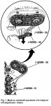
3 & 4 CAMSHAFT SPROCKET MARKS ALIGN TO LEFT OF INSPECTING GAUGE (J-42069-20)
1.Loosen the timing belt idler pulley lock bolt for camshaft sprockets 3 and 4.
2.Using GM adjustment wrench tool No. J-42060-40, or equivalent, turn the eccentric on the idler pulley counterclockwise until marks on camshaft sprocket and GM Checking Gauge tool No. J-42069-20, or equivalent, are in alignment. The high point of the idler pulley eccentric will be at approximately the 12 o'clock position.
3.Tighten the idler pulley bolt to 30 ft. lbs. Use GM tool No. J-42069-40, or equivalent, to hold eccentric in place when tightening the idler pulley bolt.
4.Remove all tools from the engine.
5.Using GM tool No. J-42098, or equivalent, rotate the engine two revolutions in the clockwise direction stopping at 60° BTDC.
6.Install GM crankshaft locking tool No. J-42069-10, or equivalent, to the crankshaft drive sprocket with the knurled bolt.
7.Turn the crankshaft until the crankshaft locking tool lever firmly contacts the water pump pulley flange. Secure the tool moveable lever to the water pump pulley flange.
8.Use GM checking gauge tool No. J-420969-20, or equivalent, to inspect the alignment of camshaft sprockets 3 and 4. The camshaft sprocket reference marks must match exactly with the checking gauge marks, Fig. 1.
9.If the sprocket timing marks are aligned with checking gauge marks, inspect adjustment of camshaft sprockets 1 and 2. If the sprocket timing marks are not aligned with the checking gauge marks, repeat procedure.
10.After all timing belt timing adjustments have been completed, proceed to "Timing Belt Tensioner Adjustment" procedure.
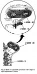
3 & 4 CAMSHAFT SPROCKET MARKS ALIGN TO RIGHT OF INSPECTING GAUGE (J-42069-20)
1.Loosen the timing belt idler pulley lock bolt for camshaft sprockets 3 and 4.
2.Using GM adjustment wrench tool No. J-42060-40, or equivalent, turn the eccentric on the idler pulley clockwise until marks on camshaft sprocket and GM Checking Gauge tool No. J-42069-20, or equivalent, are in alignment. The high point of the idler pulley eccentric will be at approximately the 12 o'clock position.
3.Tighten the idler pulley bolt to 30 ft. lbs. Use GM tool No. J-42069-40, or equivalent, to hold eccentric in place when tightening the idler pulley bolt.
4.Remove all tools from the engine.
5.Using GM tool No. J-42098, or equivalent, rotate the engine two revolutions in the clockwise direction stopping at 60° BTDC.
6.Install GM crankshaft locking tool No. J-42069-10, or equivalent, to the crankshaft drive sprocket with the knurled bolt.
7.Turn the crankshaft until the crankshaft locking tool moveable lever firmly contacts the water pump pulley flange. Secure the tool lever to the water pump pulley flange.
8.Use GM checking gauge tool No. J-420969-20, or equivalent, to inspect the alignment of the camshaft sprockets 3 and 4. The camshaft sprocket reference marks must match exactly with the checking gauge marks, Fig. 2.
9.If the sprocket timing marks are aligned with checking gauge marks, inspect adjustment of camshaft sprockets 1 and 2. If the sprocket timing marks are not aligned with checking gauge marks, repeat procedure.
10.After all timing belt timing adjustments have been completed, proceed to "Timing Belt Tensioner Adjustment" procedure.
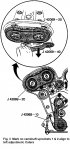
1 & 2 CAMSHAFT SPROCKET MARKS ALIGN TO LEFT OF INSPECTING GAUGE (J-42069-20)
1.Loosen the timing belt idler pulley lock bolt for camshaft sprockets 1 and 2.
2.Using GM adjustment wrench tool No. J-42060-40, or equivalent, turn the eccentric on the idler pulley counterclockwise until the camshaft sprocket marks and GM Checking Gauge tool No. J-42069-20, or equivalent, are in alignment. The high point of the idler pulley eccentric will be at approximately the 9 o'clock position.
3.Tighten the idler pulley bolt to 30 ft. lbs. Use GM tool No. J-42069-40, or equivalent, to hold the eccentric in place when tightening the idler pulley bolt.
4.Remove all tools from the engine.
5.Using GM tool No. J-42098, or equivalent, rotate the engine two revolutions in the clockwise direction stopping at 60° BTDC.
6.Install GM crankshaft locking tool No. J-42069-10, or equivalent, to the crankshaft drive sprocket with the knurled bolt.
7.Turn the crankshaft until the crankshaft locking tool moveable lever firmly contacts the water pump pulley flange. Secure the tool lever to the water pump pulley flange.
8.Use GM checking gauge tool No. J-420969-20, or equivalent, to inspect the alignment of camshaft sprockets 1 and 2. The camshaft sprocket reference marks must match exactly with the checking gauge marks, Fig. 3.
9.If the sprocket timing marks are aligned with checking gauge marks, proceed to "Timing Belt Tensioner Adjustment" procedure.
10.If the sprocket timing marks are not aligned with checking gauge marks, repeat procedure. After all timing belt timing adjustments have been completed, proceed to "Timing Belt Tensioner Adjustment" procedure.
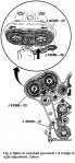
1 & 2 CAMSHAFT SPROCKET MARKS ALIGN TO RIGHT OF INSPECTING GAUGE (J-42069-20)
1.Loosen the timing belt idler pulley lock bolt for camshaft sprockets 1 and 2.
2.Using GM adjustment wrench tool No. J-42060-40, or equivalent, turn the eccentric on the idler pulley clockwise until the camshaft sprocket marks and GM Checking Gauge tool No. J-42069-20, or equivalent, are in alignment. The high point of the idler pulley eccentric will be at approximately the 9 o'clock position.
3.Tighten the idler pulley bolt to 30 ft. lbs. Use GM tool No. J-42069-40, or equivalent, to hold the eccentric in place when tightening the idler pulley bolt.
4.Remove all tools from the engine.
5.Using GM tool No. J-42098, or equivalent, rotate the engine two revolutions in the clockwise direction, stopping at 60° BTDC.
6.Install GM crankshaft locking tool No. J-42069-10, or equivalent, to the crankshaft drive sprocket with the knurled bolt.
7.Turn the crankshaft until the crankshaft locking tool moveable lever firmly contacts the water pump pulley flange. Secure the tool lever to the water pump pulley flange.
8.Use GM checking gauge tool No. J-420969-20, or equivalent, to inspect the alignment of the camshaft sprockets 1 and 2. The camshaft sprocket reference marks must match exactly with the checking gauge marks, Fig. 4.
9.If the sprocket timing marks are aligned with checking gauge marks, proceed to "Timing Belt Tensioner Adjustment" procedure.
10.If the sprocket timing marks are not aligned with checking gauge marks, repeat procedure. After all timing belt timing adjustments have been completed, proceed to "Timing Belt Tensioner Adjustment" procedure.
TIMING BELT TENSIONER ADJUSTMENT
This procedure is the completion of installing and/or adjusting the timing belt. Do not perform these steps as a "stand-alone" operation.
1.Using GM tool No. J-42069-10, or equivalent to lock the crankshaft at TDC, loosen the timing belt tensioner eccentric locknut.
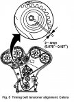
2.Turn the eccentric counterclockwise to full stop. Back off the eccentric until the reference mark is 2-4 mm above the reference mark on the flange, Fig. 5.
3.Torque the timing belt tensioner eccentric locknut to 15 ft. lbs.
4.If not done previously, use GM adjusting wrench tool No. J-42069-40, or equivalent, to hold camshaft 3 and 4 and 1 and 2 tensioner eccentrics in place and torque both idler pulley bolts to 30 ft. lbs.
5.Inspect the timing belt tensioner eccentrics. The high point of the eccentric for idler pulley for camshafts 3 and 4 should be at approximately the 12 o'clock position. The high point of the eccentric for idler pulley for camshafts 1 and 2 should be at approximately the 9 o'clock position.
6.Remove the checking gauge and crankshaft locking tool from the engine.
7.Rotate the engine in the clockwise direction two revolutions until reaching 60° BTDC.
8.Turn the crankshaft until the crankshaft locking tool lever firmly contacts the water pump pulley flange. Secure the tool lever to the water pump pulley flange.
9.Inspect the alignment of the reference marks on the camshaft sprockets with notches on the rear timing belt cover. Also inspect alignment of reference marks on crankshaft drive sprocket and oil pump housing. The alignment marks on the timing belt will no longer be aligned.
10.Use GM checking gauge tool No. J-420969-20, or equivalent, to inspect the alignment of the camshaft sprockets 3 and 4, then camshaft sprockets 1 and 2. The camshaft sprocket reference marks must match exactly with the marks on the checking gauge.
11.If the sprocket timing marks are aligned with checking gauge marks, no further adjustment is required. If the sprocket timing marks are not aligned with checking gauge marks, repeat procedure.
Catera cadillac 1997 3.0L v6
This engine is classified as an Interference engine. If the timing belt breaks or jumps timing, a piston may contact an open valve. Piston to valve contact may cause damage to the valve, piston and other engine components. In some cases valve to valve contact may be experienced when the timing belt breaks or jumps timing. To avoid belt breakage, replace the timing belt as recommended by the vehicle manufacturer timing belt replacement interval.
The following procedure is a continuation of the "Timing Belt, Replace" procedure. Always start adjustment with camshafts 3 and 4. Be ready to make several repeated adjustments and engine revolutions to arrive at the proper timing belt alignment set points.
TIMING BELT ADJUSTMENT INSPECTION
1.Use GM checking gauge tool No. J-420969-20, or equivalent, to inspect the alignment of the camshaft sprockets 3 and 4, then camshaft sprockets 1 and 2. Reference marks on camshaft sprockets must match exactly with marks on the checking gauge.
2.If the sprocket timing marks are not aligned with checking gauge marks, refer to the following applicable procedure.
3 & 4 CAMSHAFT SPROCKET MARKS ALIGN TO LEFT OF INSPECTING GAUGE (J-42069-20)
1.Loosen the timing belt idler pulley lock bolt for camshaft sprockets 3 and 4.
2.Using GM adjustment wrench tool No. J-42060-40, or equivalent, turn the eccentric on the idler pulley counterclockwise until marks on camshaft sprocket and GM Checking Gauge tool No. J-42069-20, or equivalent, are in alignment. The high point of the idler pulley eccentric will be at approximately the 12 o'clock position.
3.Tighten the idler pulley bolt to 30 ft. lbs. Use GM tool No. J-42069-40, or equivalent, to hold eccentric in place when tightening the idler pulley bolt.
4.Remove all tools from the engine.
5.Using GM tool No. J-42098, or equivalent, rotate the engine two revolutions in the clockwise direction stopping at 60° BTDC.
6.Install GM crankshaft locking tool No. J-42069-10, or equivalent, to the crankshaft drive sprocket with the knurled bolt.
7.Turn the crankshaft until the crankshaft locking tool lever firmly contacts the water pump pulley flange. Secure the tool moveable lever to the water pump pulley flange.
8.Use GM checking gauge tool No. J-420969-20, or equivalent, to inspect the alignment of camshaft sprockets 3 and 4. The camshaft sprocket reference marks must match exactly with the checking gauge marks, Fig. 1.
9.If the sprocket timing marks are aligned with checking gauge marks, inspect adjustment of camshaft sprockets 1 and 2. If the sprocket timing marks are not aligned with the checking gauge marks, repeat procedure.
10.After all timing belt timing adjustments have been completed, proceed to "Timing Belt Tensioner Adjustment" procedure.
3 & 4 CAMSHAFT SPROCKET MARKS ALIGN TO RIGHT OF INSPECTING GAUGE (J-42069-20)
1.Loosen the timing belt idler pulley lock bolt for camshaft sprockets 3 and 4.
2.Using GM adjustment wrench tool No. J-42060-40, or equivalent, turn the eccentric on the idler pulley clockwise until marks on camshaft sprocket and GM Checking Gauge tool No. J-42069-20, or equivalent, are in alignment. The high point of the idler pulley eccentric will be at approximately the 12 o'clock position.
3.Tighten the idler pulley bolt to 30 ft. lbs. Use GM tool No. J-42069-40, or equivalent, to hold eccentric in place when tightening the idler pulley bolt.
4.Remove all tools from the engine.
5.Using GM tool No. J-42098, or equivalent, rotate the engine two revolutions in the clockwise direction stopping at 60° BTDC.
6.Install GM crankshaft locking tool No. J-42069-10, or equivalent, to the crankshaft drive sprocket with the knurled bolt.
7.Turn the crankshaft until the crankshaft locking tool moveable lever firmly contacts the water pump pulley flange. Secure the tool lever to the water pump pulley flange.
8.Use GM checking gauge tool No. J-420969-20, or equivalent, to inspect the alignment of the camshaft sprockets 3 and 4. The camshaft sprocket reference marks must match exactly with the checking gauge marks, Fig. 2.
9.If the sprocket timing marks are aligned with checking gauge marks, inspect adjustment of camshaft sprockets 1 and 2. If the sprocket timing marks are not aligned with checking gauge marks, repeat procedure.
10.After all timing belt timing adjustments have been completed, proceed to "Timing Belt Tensioner Adjustment" procedure.
1 & 2 CAMSHAFT SPROCKET MARKS ALIGN TO LEFT OF INSPECTING GAUGE (J-42069-20)
1.Loosen the timing belt idler pulley lock bolt for camshaft sprockets 1 and 2.
2.Using GM adjustment wrench tool No. J-42060-40, or equivalent, turn the eccentric on the idler pulley counterclockwise until the camshaft sprocket marks and GM Checking Gauge tool No. J-42069-20, or equivalent, are in alignment. The high point of the idler pulley eccentric will be at approximately the 9 o'clock position.
3.Tighten the idler pulley bolt to 30 ft. lbs. Use GM tool No. J-42069-40, or equivalent, to hold the eccentric in place when tightening the idler pulley bolt.
4.Remove all tools from the engine.
5.Using GM tool No. J-42098, or equivalent, rotate the engine two revolutions in the clockwise direction stopping at 60° BTDC.
6.Install GM crankshaft locking tool No. J-42069-10, or equivalent, to the crankshaft drive sprocket with the knurled bolt.
7.Turn the crankshaft until the crankshaft locking tool moveable lever firmly contacts the water pump pulley flange. Secure the tool lever to the water pump pulley flange.
8.Use GM checking gauge tool No. J-420969-20, or equivalent, to inspect the alignment of camshaft sprockets 1 and 2. The camshaft sprocket reference marks must match exactly with the checking gauge marks, Fig. 3.
9.If the sprocket timing marks are aligned with checking gauge marks, proceed to "Timing Belt Tensioner Adjustment" procedure.
10.If the sprocket timing marks are not aligned with checking gauge marks, repeat procedure. After all timing belt timing adjustments have been completed, proceed to "Timing Belt Tensioner Adjustment" procedure.
1 & 2 CAMSHAFT SPROCKET MARKS ALIGN TO RIGHT OF INSPECTING GAUGE (J-42069-20)
1.Loosen the timing belt idler pulley lock bolt for camshaft sprockets 1 and 2.
2.Using GM adjustment wrench tool No. J-42060-40, or equivalent, turn the eccentric on the idler pulley clockwise until the camshaft sprocket marks and GM Checking Gauge tool No. J-42069-20, or equivalent, are in alignment. The high point of the idler pulley eccentric will be at approximately the 9 o'clock position.
3.Tighten the idler pulley bolt to 30 ft. lbs. Use GM tool No. J-42069-40, or equivalent, to hold the eccentric in place when tightening the idler pulley bolt.
4.Remove all tools from the engine.
5.Using GM tool No. J-42098, or equivalent, rotate the engine two revolutions in the clockwise direction, stopping at 60° BTDC.
6.Install GM crankshaft locking tool No. J-42069-10, or equivalent, to the crankshaft drive sprocket with the knurled bolt.
7.Turn the crankshaft until the crankshaft locking tool moveable lever firmly contacts the water pump pulley flange. Secure the tool lever to the water pump pulley flange.
8.Use GM checking gauge tool No. J-420969-20, or equivalent, to inspect the alignment of the camshaft sprockets 1 and 2. The camshaft sprocket reference marks must match exactly with the checking gauge marks, Fig. 4.
9.If the sprocket timing marks are aligned with checking gauge marks, proceed to "Timing Belt Tensioner Adjustment" procedure.
10.If the sprocket timing marks are not aligned with checking gauge marks, repeat procedure. After all timing belt timing adjustments have been completed, proceed to "Timing Belt Tensioner Adjustment" procedure.
TIMING BELT TENSIONER ADJUSTMENT
This procedure is the completion of installing and/or adjusting the timing belt. Do not perform these steps as a "stand-alone" operation.
1.Using GM tool No. J-42069-10, or equivalent to lock the crankshaft at TDC, loosen the timing belt tensioner eccentric locknut.
2.Turn the eccentric counterclockwise to full stop. Back off the eccentric until the reference mark is 2-4 mm above the reference mark on the flange, Fig. 5.
3.Torque the timing belt tensioner eccentric locknut to 15 ft. lbs.
4.If not done previously, use GM adjusting wrench tool No. J-42069-40, or equivalent, to hold camshaft 3 and 4 and 1 and 2 tensioner eccentrics in place and torque both idler pulley bolts to 30 ft. lbs.
5.Inspect the timing belt tensioner eccentrics. The high point of the eccentric for idler pulley for camshafts 3 and 4 should be at approximately the 12 o'clock position. The high point of the eccentric for idler pulley for camshafts 1 and 2 should be at approximately the 9 o'clock position.
6.Remove the checking gauge and crankshaft locking tool from the engine.
7.Rotate the engine in the clockwise direction two revolutions until reaching 60° BTDC.
8.Turn the crankshaft until the crankshaft locking tool lever firmly contacts the water pump pulley flange. Secure the tool lever to the water pump pulley flange.
9.Inspect the alignment of the reference marks on the camshaft sprockets with notches on the rear timing belt cover. Also inspect alignment of reference marks on crankshaft drive sprocket and oil pump housing. The alignment marks on the timing belt will no longer be aligned.
10.Use GM checking gauge tool No. J-420969-20, or equivalent, to inspect the alignment of the camshaft sprockets 3 and 4, then camshaft sprockets 1 and 2. The camshaft sprocket reference marks must match exactly with the marks on the checking gauge.
11.If the sprocket timing marks are aligned with checking gauge marks, no further adjustment is required. If the sprocket timing marks are not aligned with checking gauge marks, repeat procedure.
Adjuntos
- Estado
- Cerrado para nuevas respuestas.
Siguenos en:
El contenido de especificaciones técnicas,comentarios, opiniones y otros datos en este foro sólo son con fines informativos y son de exclusiva responsabilidad de cada usuario. Foromecanicos.com no puede y no verifica ni garantiza la exactitud o exhaustividad de la información. Usted utiliza este sitio web bajo su propio riesgo y solo con fines informativos. Las marcas y los logotipos de los fabricantes de automóviles en esta página web son propiedad de los titulares de las mismas.
Usamos cookies.Si continúas utilizando este sitio, estás consintiendo utilizar cookies.