Comparto instrucciones para reemplazo de Cabeza
Toyota Previa LE 2.4L 4 cil 2TZ-FZE
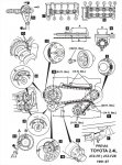
CYLINDER HEAD, REPLACE
1.Disconnect battery ground cable.
2.Remove engine harness cover attaching bolts, then disconnect.
3.Disconnect pressure regulator vacuum hose.
4.Disconnect the following electrical connectors:
a.Oil pressure switch.
b.Oil level sensor.
c.Distributor connector.
d.Start injector time switch.
e.On California models, EGR gas temperature sensor.
f.On all models, water temperature sensor and sender gauge.
g.Knock sensor.
h.Four injector connectors.
5.Remove No. 2 cylinder head cover.
6.Disconnect No. 2 and 3 air hoses, then remove distributor.
7.Remove EGR valve, pipe and gaskets.
8.Remove delivery pipe and cold start injector union bolts and gaskets, then pressure regulator and hose, then remove fuel pipe.
9.Remove water outlet and No. 2 water bypass pipe and gasket.
10.Remove PCV hose.
11.Remove delivery pipe.
12.Disconnect water pump hose, the remove intake manifold brackets and manifold.
13.Remove RH engine mount.
14.Remove exhaust manifold attaching nuts, then remove.
15.Remove RH engine mount.
16.Remove exhaust manifold heat insulator.
17.Remove No. 1 oil return pipe.
18.Remove No. 1 cylinder head cover, then half circular plugs.
19.Place installation alignment marks on camshaft sprocket and chain.
20.Hold camshaft, then remove cam sprocket bolt.
21.Remove chain tensioner and gasket, remove cam sprocket and chain. Do not remove slipper and damper.
22.Remove No. 6 bearing cap bolt.
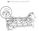
23.Remove exhaust camshafts as follows:
a.Camshaft must be held level during removal or cylinder head damage may result.
b.Set exhaust knock pin hole at 5-30° BTDC, Fig. 1.
c.Install service bolt to camshaft sub-gear and main gear.
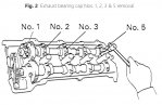
d.Alternately and uniformly loosen and remove Nos. 1, 2, 3 and 5 bearing caps in sequence shown Fig. 2.
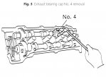
e.Alternately and uniformly loosen No. 4 bearing cap bolt, Fig. 3, ensure camshaft is being lifted straight out, if not retighten No. 4 cap and reverse camshaft removal procedure. Do not pry or force camshaft.
f.Remove No. 4 bearing cap and exhaust camshaft.
24.Remove intake camshafts as follows:
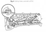
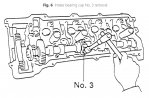
a.Set exhaust knock pin hole at 75-100° BTDC, Fig. 4.
b.Install service bolt to camshaft sub-gear and main gear.
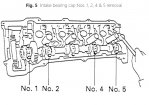
c.Alternately and uniformly loosen and remove Nos. 1, 2, 4 and 5 bearing caps in sequence shown Fig. 5.
d.Alternately and uniformly loosen No. 3 bearing cap bolt, Fig. 6,ensure camshaft is being lifted straight out, if not retighten No. 3 cap and reverse camshaft removal procedure. Do not pry or force camshaft.
e.Remove No. 3 bearing cap and exhaust camshaft.
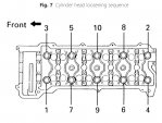
25.Remove two front cylinder head bolts, then remove cylinder head bolts, in sequence Fig. 7, in two or three steps.
26.Reverse procedure to install, noting the following:
a.Torque cylinder head bolts in reverse removal sequence, Fig. 7, in three step to 29 ft. lbs., then mark top front side of each bolt, then tighten an additional 90°, ensuring alignment mark is facing side ward, then tighten and additional 90°, ensuring alignment mark is facing rearward.
b.Torque two front cylinder head bolts to 15 ft. lbs.
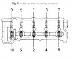
c.Torque intake bearing caps in sequence shown, Fig. 8, in three steps to 12 ft. lbs.
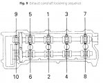
d.Torque exhaust bearing caps in sequence shown, Fig. 9, in three steps to 12 ft. lbs.
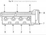
e.Torque cylinder head cover bolts in sequence shown, Fig. 10, to 69 inch lbs.