-
Hola Invitado, Foromecanicos es el Foro de Automecanico y Autoelectronico - informacion sobre mecanica automotriz, computers, encendido y auto electronics, diagramas.
Estás utilizando un navegador obsoleto. Este u otros sitios web pueden no ser mostrados correctamente.
Debes actualizarlo o utilizar un navegador alternativo.
Debes actualizarlo o utilizar un navegador alternativo.
Torques
- Iniciador del tema llermo
- Fecha de inicio
-
- Etiquetas
- toyota hiase
Tobe82
Experto
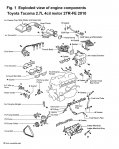
Hola, esta informacion puede servir de apoyo, es para Toyota Tacoma 2.7L 4cil motor 2TR-FE 2010
CYLINDER HEAD, REPLACE
1.On models equipped with audio coded anti-theft system, obtain three-digit system code.
2.On all models, drain coolant from engine.
3.Remove MAF sensor, IAT sensor, air hose and upper air cleaner as a unit, then the lower air cleaner housing, Fig. 1.
4.Disconnect throttle cable from throttle body, then remove intake air connector tube.
5.On models equipped with A/C, remove A/C idle-up valve.
6.On models equipped with power steering, proceed as follows:
a.Remove power steering belt and idler pulley.
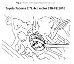
b.Remove power steering pump pulley using flexible Y wrench, tool No. 09960-10010, or equivalent, to hold pulley, Fig. 2.
c.Then, without disconnecting hoses, remove power steering pump and position aside.
d.Remove power steering pump mounting bracket.
7.On all models, disconnect spark plug wires, then disconnect and remove complete distributor.
8.Disconnect and remove water outlet and ECT sender form engine as a unit.
9.Disconnect and remove all connectors and hoses from throttle body, then remove throttle body.
10.Disconnect all electrical connectors and wiring attached to cylinder head and components.
11.Disconnect heater bypass hose, then remove cylinder head rear cover.
12.Remove EGR valve, vacuum modulator and connecting pipe, disconnecting required water and vacuum lines.
13.Remove intake chamber stay, then the fuel return pipe. When disconnecting fuel lines use a suitable container to collect any spilled fuel, loosen fuel connections slowly to allow pressure to bleed off.
14.Remove bolts to remove intake air chamber from intake manifold, then the fuel inlet tube.
15.Remove fuel delivery pipe and injectors as a unit, then the intake manifold.
16.Disconnect both oxygen sensor connectors, then remove front exhaust pipe.
17.Remove exhaust manifold, then the No. 1 and No. 2 engine hanger hooks.
18.Remove cylinder head cover, then the spark plugs.
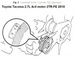
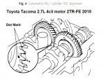
19.Turning engine clockwise, set No. 1 cylinder to TDC compression stroke, Figs. 3 and 4. Remove timing chain tensioner.
20.Remove two rubber semi-circular plugs from head, then place a suitable wrench on the hex part of exhaust camshaft, remove distributor gear and bolt.
21.Place a suitable wrench on hex part of intake camshaft, then remove cam drive sprocket and bolt. Allow chain and sprocket to rest on chain guide rails.
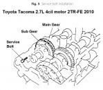
22.Turn exhaust camshaft with a suitable wrench until service bolt hole is accessible, Fig. 5. Install a 6 X 1.0 X 16-20 mm bolt into service hole to secure spring loaded sub gear to main exhaust camshaft gear.
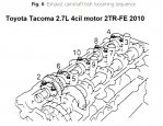
a.Loosen camshaft bearing caps in several stages in sequence outlined in Fig. 6, then remove bearing caps.
b.Camshaft must be lifted from head straight and level. Do not pry or use force. Due to tight tolerances, if cam is not lifted out of cylinder head straight and level, cam or head breakage could occur. If binding occurs reinstall No. 3 bearing cap, lightly tighten bolts, then while lifting cam gear, loosen bearing cap bolts evenly to allow camshaft to come out of head straight and level.
c.Repeat steps a and b above to remove intake camshaft, using sequence outlined in Fig. 7 to loosen bearing caps.
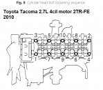
23.Remove two cylinder head bolts located inside front of cam chain passage, then loosen cylinder head bolts in several stages in sequence outlined in Fig. 8.
24.Lift cylinder head up off of dowel pins to remove from engine.
25.Remove and store, keeping together in order, lifters, adjustment shims, valves, valve springs and retainers.
CYLINDER HEAD, REPLACE
1.On models equipped with audio coded anti-theft system, obtain three-digit system code.
2.On all models, drain coolant from engine.
3.Remove MAF sensor, IAT sensor, air hose and upper air cleaner as a unit, then the lower air cleaner housing, Fig. 1.
4.Disconnect throttle cable from throttle body, then remove intake air connector tube.
5.On models equipped with A/C, remove A/C idle-up valve.
6.On models equipped with power steering, proceed as follows:
a.Remove power steering belt and idler pulley.
b.Remove power steering pump pulley using flexible Y wrench, tool No. 09960-10010, or equivalent, to hold pulley, Fig. 2.
c.Then, without disconnecting hoses, remove power steering pump and position aside.
d.Remove power steering pump mounting bracket.
7.On all models, disconnect spark plug wires, then disconnect and remove complete distributor.
8.Disconnect and remove water outlet and ECT sender form engine as a unit.
9.Disconnect and remove all connectors and hoses from throttle body, then remove throttle body.
10.Disconnect all electrical connectors and wiring attached to cylinder head and components.
11.Disconnect heater bypass hose, then remove cylinder head rear cover.
12.Remove EGR valve, vacuum modulator and connecting pipe, disconnecting required water and vacuum lines.
13.Remove intake chamber stay, then the fuel return pipe. When disconnecting fuel lines use a suitable container to collect any spilled fuel, loosen fuel connections slowly to allow pressure to bleed off.
14.Remove bolts to remove intake air chamber from intake manifold, then the fuel inlet tube.
15.Remove fuel delivery pipe and injectors as a unit, then the intake manifold.
16.Disconnect both oxygen sensor connectors, then remove front exhaust pipe.
17.Remove exhaust manifold, then the No. 1 and No. 2 engine hanger hooks.
18.Remove cylinder head cover, then the spark plugs.
19.Turning engine clockwise, set No. 1 cylinder to TDC compression stroke, Figs. 3 and 4. Remove timing chain tensioner.
20.Remove two rubber semi-circular plugs from head, then place a suitable wrench on the hex part of exhaust camshaft, remove distributor gear and bolt.
21.Place a suitable wrench on hex part of intake camshaft, then remove cam drive sprocket and bolt. Allow chain and sprocket to rest on chain guide rails.
22.Turn exhaust camshaft with a suitable wrench until service bolt hole is accessible, Fig. 5. Install a 6 X 1.0 X 16-20 mm bolt into service hole to secure spring loaded sub gear to main exhaust camshaft gear.
a.Loosen camshaft bearing caps in several stages in sequence outlined in Fig. 6, then remove bearing caps.
b.Camshaft must be lifted from head straight and level. Do not pry or use force. Due to tight tolerances, if cam is not lifted out of cylinder head straight and level, cam or head breakage could occur. If binding occurs reinstall No. 3 bearing cap, lightly tighten bolts, then while lifting cam gear, loosen bearing cap bolts evenly to allow camshaft to come out of head straight and level.
c.Repeat steps a and b above to remove intake camshaft, using sequence outlined in Fig. 7 to loosen bearing caps.
23.Remove two cylinder head bolts located inside front of cam chain passage, then loosen cylinder head bolts in several stages in sequence outlined in Fig. 8.
24.Lift cylinder head up off of dowel pins to remove from engine.
25.Remove and store, keeping together in order, lifters, adjustment shims, valves, valve springs and retainers.
Adjuntos
-
 toyota_tacoma_27_cylinderhead_1.jpg257,5 KB · Visitas: 368
 -
 toyota_tacoma_27_cylinderhead_2.jpg122,2 KB · Visitas: 270
 -
 toyota_tacoma_27_cylinderhead_3.jpg104,8 KB · Visitas: 253
 -
 toyota_tacoma_27_cylinderhead_4.jpg118,7 KB · Visitas: 278
 -
 toyota_tacoma_27_cylinderhead_5.jpg108,2 KB · Visitas: 453
 -
 toyota_tacoma_27_cylinderhead_6.jpg107,2 KB · Visitas: 300
 -
 toyota_tacoma_27_cylinderhead_7.jpg89,9 KB · Visitas: 293
 -
 toyota_tacoma_27_cylinderhead_8.jpg89,9 KB · Visitas: 264
Tobe82
Experto
continua...
26.Reverse procedure to install, noting the following:
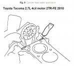
a.Tighten all fasteners to specifications. Before installing head gasket, apply a suitable sealer to areas outlined in Fig. 9, then place head gasket and cylinder head onto block.
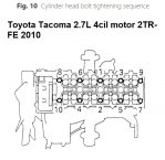
b.Install cylinder head bolts with lightly oiled threads. Using sequence outlined in Fig. 10, torque bolts in three steps: first, to 29 ft. lbs; then an additional 90°; and finally, an additional 90°.
c.Install two cylinder head bolts located at front of cam chain well. Torque bolts to 15 ft. lbs.
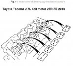
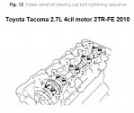
d.Install intake camshaft first. Lightly grease thrust bearing surfaces with a MP grease. Ensure bearing caps are installed as outlined in Fig. 11, with dowel pin, on drive sprocket flange pointing up. Tighten bearing cap bolts in several stages, Fig. 12, then torque bearing cap bolts to 12 ft. lbs., in sequence outlined.
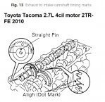
e.Install exhaust camshaft using above procedure. Ensure timing marks on camshaft gears are aligned, Fig. 13. After bearing cap bolts have been tightened, remove exhaust camshaft gear service bolt.
f.Set engine to TDC No. 1 cylinder, Fig. 3.
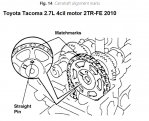
g.Align matchmarks on timing chain to sprocket, then install sprocket to camshaft, Fig. 14.
h.Holding intake camshaft with suitable wrench torque sprocket bolt to 54 ft. lbs. Install distributor drive gear, then holding exhaust camshaft with a suitable wrench torque drive gear bolt to 34 ft. lbs.
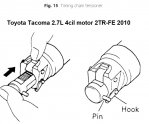
i.Compress and hook chain tensioner pin, Fig. 15, then install tensioner. Release tensioner by turning crankshaft counterclockwise or by pressing in on tensioner rail with a screwdriver so that tensioner hook is released.
j.Use new O-rings when installing fuel injectors and distributor. Refer to "Valve Adjustment" for procedures.
k.Reset audio coded anti-theft system, if equipped, as outlined under "Precautions."
26.Reverse procedure to install, noting the following:
a.Tighten all fasteners to specifications. Before installing head gasket, apply a suitable sealer to areas outlined in Fig. 9, then place head gasket and cylinder head onto block.
b.Install cylinder head bolts with lightly oiled threads. Using sequence outlined in Fig. 10, torque bolts in three steps: first, to 29 ft. lbs; then an additional 90°; and finally, an additional 90°.
c.Install two cylinder head bolts located at front of cam chain well. Torque bolts to 15 ft. lbs.
d.Install intake camshaft first. Lightly grease thrust bearing surfaces with a MP grease. Ensure bearing caps are installed as outlined in Fig. 11, with dowel pin, on drive sprocket flange pointing up. Tighten bearing cap bolts in several stages, Fig. 12, then torque bearing cap bolts to 12 ft. lbs., in sequence outlined.
e.Install exhaust camshaft using above procedure. Ensure timing marks on camshaft gears are aligned, Fig. 13. After bearing cap bolts have been tightened, remove exhaust camshaft gear service bolt.
f.Set engine to TDC No. 1 cylinder, Fig. 3.
g.Align matchmarks on timing chain to sprocket, then install sprocket to camshaft, Fig. 14.
h.Holding intake camshaft with suitable wrench torque sprocket bolt to 54 ft. lbs. Install distributor drive gear, then holding exhaust camshaft with a suitable wrench torque drive gear bolt to 34 ft. lbs.
i.Compress and hook chain tensioner pin, Fig. 15, then install tensioner. Release tensioner by turning crankshaft counterclockwise or by pressing in on tensioner rail with a screwdriver so that tensioner hook is released.
j.Use new O-rings when installing fuel injectors and distributor. Refer to "Valve Adjustment" for procedures.
k.Reset audio coded anti-theft system, if equipped, as outlined under "Precautions."
Adjuntos
-
 toyota_tacoma_27_cylinderhead_9.jpg87,4 KB · Visitas: 256
 -
 toyota_tacoma_27_cylinderhead_010.jpg71,9 KB · Visitas: 273
 -
 toyota_tacoma_27_cylinderhead_011.jpg112,2 KB · Visitas: 258
 -
 toyota_tacoma_27_cylinderhead_012.jpg82,9 KB · Visitas: 235
 -
 toyota_tacoma_27_cylinderhead_013.jpg109,9 KB · Visitas: 288
 -
 toyota_tacoma_27_cylinderhead_014.jpg138,5 KB · Visitas: 335
 -
 toyota_tacoma_27_cylinderhead_015.jpg80 KB · Visitas: 272
Siguenos en:
El contenido de especificaciones técnicas,comentarios, opiniones y otros datos en este foro sólo son con fines informativos y son de exclusiva responsabilidad de cada usuario. Foromecanicos.com no puede y no verifica ni garantiza la exactitud o exhaustividad de la información. Usted utiliza este sitio web bajo su propio riesgo y solo con fines informativos. Las marcas y los logotipos de los fabricantes de automóviles en esta página web son propiedad de los titulares de las mismas.
Usamos cookies.Si continúas utilizando este sitio, estás consintiendo utilizar cookies.