Tobe82
Experto
Ayuda con el diagrama de puesta a punto para un Mercedes Benz c240 año 2001, leí en un mensaje. Comparto la informacion para
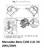
Mercedes Benz C240 2.6L V6 2001/2005
TIMING CHAIN, REPLACE
Caution: This procedure has been revised by a Technical Service Bulletin.
113 engine does not use a balance shaft.
1.Remove one spark plug from each cylinder.
2.Remove valve covers.
3.position engine with cylinder No. 1 at 40° after TDC, Fig. 1, noting the following:
a.Caution: Do not crank engine backward.
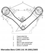
b.Because of unevenly long timing chain travel path, it may be required to crank engine up to 14 times before chain copper plates align with camshaft sprocket marks.
c.Lefthand and righthand camshaft grooves point in direction of inner V and are centered on cylinder head cover mating surface.
d.On models equipped with air pump, remove combination valve mounting bolts before inserting righthand locating plate.
e.On all models, install two locating plate tools No. 112 589 00 32 00, or equivalent, flush onto lefthand and righthand cylinder heads and into camshaft slots.
f.Balance shaft crankcase front and balancing weight marks must align. Marks can be seen through lefthand timing case shaft approximately .867 inch below cylinder head and valve cover parting surface when cylinder head is removed.
g.Remove locking plates.
4.Remove chain tensioner.
5.Remove Camshaft Position (CMP) sensor.
6.Crank engine in rotational direction until separating link can easily be accessed. Link is on righthand side of copper plate.
7.Remove righthand camshaft bearing bridge.
8.Install holding bush tool No. 112 589 05 04 00, or equivalent, onto righthand camshaft. Tighten bolts until they contact.
9.Install holding tools No. 112 589 04 40 00, or equivalent, onto lefthand and righthand cylinder heads.
10.Separate and remove timing chain.
11.Cover timing case recess with suitable clean cloth. Caution: Components dropped into timing case must be removed.
Mercedes Benz C240 2.6L V6 2001/2005
TIMING CHAIN, REPLACE
Caution: This procedure has been revised by a Technical Service Bulletin.
113 engine does not use a balance shaft.
1.Remove one spark plug from each cylinder.
2.Remove valve covers.
3.position engine with cylinder No. 1 at 40° after TDC, Fig. 1, noting the following:
a.Caution: Do not crank engine backward.
b.Because of unevenly long timing chain travel path, it may be required to crank engine up to 14 times before chain copper plates align with camshaft sprocket marks.
c.Lefthand and righthand camshaft grooves point in direction of inner V and are centered on cylinder head cover mating surface.
d.On models equipped with air pump, remove combination valve mounting bolts before inserting righthand locating plate.
e.On all models, install two locating plate tools No. 112 589 00 32 00, or equivalent, flush onto lefthand and righthand cylinder heads and into camshaft slots.
f.Balance shaft crankcase front and balancing weight marks must align. Marks can be seen through lefthand timing case shaft approximately .867 inch below cylinder head and valve cover parting surface when cylinder head is removed.
g.Remove locking plates.
4.Remove chain tensioner.
5.Remove Camshaft Position (CMP) sensor.
6.Crank engine in rotational direction until separating link can easily be accessed. Link is on righthand side of copper plate.
7.Remove righthand camshaft bearing bridge.
8.Install holding bush tool No. 112 589 05 04 00, or equivalent, onto righthand camshaft. Tighten bolts until they contact.
9.Install holding tools No. 112 589 04 40 00, or equivalent, onto lefthand and righthand cylinder heads.
10.Separate and remove timing chain.
11.Cover timing case recess with suitable clean cloth. Caution: Components dropped into timing case must be removed.