Tobe82
Experto
Cadena de Tiempo Toyota Camry 2.4L 4 cil (2AZ-FE), comparto diagramas y manual. Sirve tambien para Toyota Camry & Solara 2.4L 4cil (2AZ-FE) 2006-2011
TIMING CHAIN GUIDE R&R
REMOVAL
Caution: Do not attempt to hang the engine by hooking the chain to any other component.
Be careful not to damage the contact surfaces of the crankcase, chain cover and oil pan.
Do not turn the crankshaft without the chain tensioner.
Do not lift the engine more than required.
1.Disconnect cable from battery ground terminal.
2.Remove No. 1 engine cover sub-assembly.
3.Remove righthand front wheel.
4.Remove lefthand engine under cover.
5.Remove righthand engine under cover.
6.Remove righthand front fender apron seal.
7.Drain engine oil.
8.Remove front exhaust pipe assembly.
9.Remove No. 2 righthand engine mounting stay.
10.Remove engine moving control rod sub-assembly.
11.Remove No. 2 righthand engine mounting bracket.
12.Remove v-ribbed belt.
13.Remove alternator assembly.
14.Remove vane pump assembly.
15.Remove ignition coil assembly.
16.Disconnect ventilation hose.
17.Disconnect No. 2 ventilation hose.
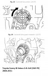
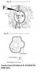
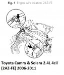
18.Remove the two bolts and disconnect the two engine wires, Fig. 1.
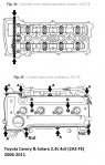
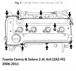
19.Remove the eight bolts, two nuts, and cylinder head cover, Fig. 2.
20.Set No. 1 cylinder to TDC/compression.
21.Remove crankshaft pulley.
22.Remove crank position sensor.
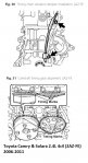
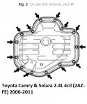
23.Remove the oil pan 12 bolts and two nuts, Fig. 3.
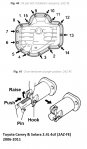
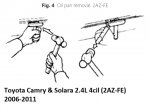
24.Insert the blade of an oil pan seal cutter between the crankcase and oil pan. Cut through the sealer and remove the oil pan, Fig. 4.
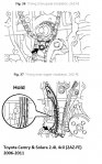
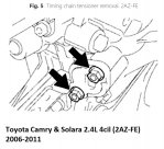
25.Remove the two nuts, No. 1 chain tensioner and gasket, Fig. 5.
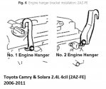
26.Install the No. 1 engine hanger and No. 2 engine hanger with the bolts. Torque bolts to 28 ft. lbs., Fig. 6.
27.Attach a sling device to the engine hangers and chain block.
28.Lift the engine upward using the chain block.
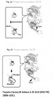
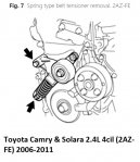
29.Remove the bolt, nut and spring type belt tensioner, Fig. 7.
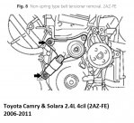
30.Remove the bolt, nut and non-spring type belt tensioner, Fig. 8.
31.Attach the engine chain hoist to the engine hangers.
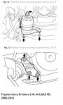
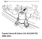
32.Remove the bolt and disconnect the front engine mounting insulator, Fig. 9.
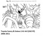
33.On models equipped with manual transaxle, remove the bolt and disconnect the engine lateral control rod, Fig. 10.
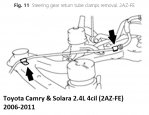
34.On all models, remove the two bolts and disconnect the steering gear return tube clamps from the frame, Fig. 11.
35.Remove the four nuts from the righthand engine mounting insulator, Fig. 12.
36.Raise the engine and remove the righthand engine mounting insulator, Fig. 12.
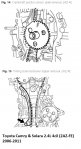
37.Remove the three bolts and righthand engine mounting bracket, Fig. 13.
38.Remove timing chain cover sub-assembly.
39.Remove timing chain case oil seal.
40.Remove the crankshaft position sensor plate, Fig. 14.
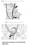
41.Remove the bolt and chain tensioner slipper, Fig. 15.
42.Remove the two bolts and chain vibration damper, Fig. 16.
43.Remove the bolt and timing chain guide, Fig. 17.
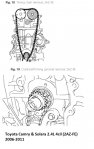
44.Remove the chain sub-assembly, Fig. 18.
45.Remove the crankshaft timing sprocket, Fig. 19.
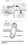
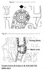
46.Turn the crankshaft by 90° counterclockwise to align the adjusting hole of the oil pump drive shaft sprocket with the groove of the oil pump, Fig. 20.
47.Insert a 4 mm diameter pin into the adjusting hole of the oil pump drive shaft sprocket to lock the gear in position, and then remove the nut, Fig. 21.
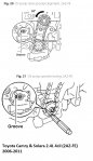
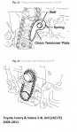
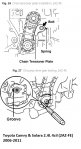
48.Remove the bolt, chain tensioner plate and spring, Fig. 22.
49.Remove the chain tensioner, oil pump driven sprocket and chain, Fig. 23.
TIMING CHAIN GUIDE R&R
REMOVAL
Caution: Do not attempt to hang the engine by hooking the chain to any other component.
Be careful not to damage the contact surfaces of the crankcase, chain cover and oil pan.
Do not turn the crankshaft without the chain tensioner.
Do not lift the engine more than required.
1.Disconnect cable from battery ground terminal.
2.Remove No. 1 engine cover sub-assembly.
3.Remove righthand front wheel.
4.Remove lefthand engine under cover.
5.Remove righthand engine under cover.
6.Remove righthand front fender apron seal.
7.Drain engine oil.
8.Remove front exhaust pipe assembly.
9.Remove No. 2 righthand engine mounting stay.
10.Remove engine moving control rod sub-assembly.
11.Remove No. 2 righthand engine mounting bracket.
12.Remove v-ribbed belt.
13.Remove alternator assembly.
14.Remove vane pump assembly.
15.Remove ignition coil assembly.
16.Disconnect ventilation hose.
17.Disconnect No. 2 ventilation hose.
18.Remove the two bolts and disconnect the two engine wires, Fig. 1.
19.Remove the eight bolts, two nuts, and cylinder head cover, Fig. 2.
20.Set No. 1 cylinder to TDC/compression.
21.Remove crankshaft pulley.
22.Remove crank position sensor.
23.Remove the oil pan 12 bolts and two nuts, Fig. 3.
24.Insert the blade of an oil pan seal cutter between the crankcase and oil pan. Cut through the sealer and remove the oil pan, Fig. 4.
25.Remove the two nuts, No. 1 chain tensioner and gasket, Fig. 5.
26.Install the No. 1 engine hanger and No. 2 engine hanger with the bolts. Torque bolts to 28 ft. lbs., Fig. 6.
27.Attach a sling device to the engine hangers and chain block.
28.Lift the engine upward using the chain block.
29.Remove the bolt, nut and spring type belt tensioner, Fig. 7.
30.Remove the bolt, nut and non-spring type belt tensioner, Fig. 8.
31.Attach the engine chain hoist to the engine hangers.
32.Remove the bolt and disconnect the front engine mounting insulator, Fig. 9.
33.On models equipped with manual transaxle, remove the bolt and disconnect the engine lateral control rod, Fig. 10.
34.On all models, remove the two bolts and disconnect the steering gear return tube clamps from the frame, Fig. 11.
35.Remove the four nuts from the righthand engine mounting insulator, Fig. 12.
36.Raise the engine and remove the righthand engine mounting insulator, Fig. 12.
37.Remove the three bolts and righthand engine mounting bracket, Fig. 13.
38.Remove timing chain cover sub-assembly.
39.Remove timing chain case oil seal.
40.Remove the crankshaft position sensor plate, Fig. 14.
41.Remove the bolt and chain tensioner slipper, Fig. 15.
42.Remove the two bolts and chain vibration damper, Fig. 16.
43.Remove the bolt and timing chain guide, Fig. 17.
44.Remove the chain sub-assembly, Fig. 18.
45.Remove the crankshaft timing sprocket, Fig. 19.
46.Turn the crankshaft by 90° counterclockwise to align the adjusting hole of the oil pump drive shaft sprocket with the groove of the oil pump, Fig. 20.
47.Insert a 4 mm diameter pin into the adjusting hole of the oil pump drive shaft sprocket to lock the gear in position, and then remove the nut, Fig. 21.
48.Remove the bolt, chain tensioner plate and spring, Fig. 22.
49.Remove the chain tensioner, oil pump driven sprocket and chain, Fig. 23.
Adjuntos
-
 toyota_camry_2AZFE_timingchain_1.jpg70,1 KB · Visitas: 571
 -
 toyota_camry_2AZFE_timingchain_4.jpg50,2 KB · Visitas: 659
 -
 toyota_camry_2AZFE_timingchain_5.jpg85,4 KB · Visitas: 462
 -
 toyota_camry_2AZFE_timingchain_6.jpg75,7 KB · Visitas: 466
 -
 toyota_camry_2AZFE_timingchain_7.jpg72,2 KB · Visitas: 563
 -
 toyota_camry_2AZFE_timingchain_8.jpg97,2 KB · Visitas: 500
 -
 toyota_camry_2AZFE_timingchain_9.jpg80 KB · Visitas: 494
 -
 toyota_camry_2AZFE_timingchain_010.jpg102,2 KB · Visitas: 473
 -
 toyota_camry_2AZFE_timingchain_011.jpg62,6 KB · Visitas: 489
 -
 toyota_camry_2AZFE_timingchain_3.jpg72,4 KB · Visitas: 906
 -
 toyota_camry_2AZFE_timingchain_4.jpg50,2 KB · Visitas: 624
 -
 toyota_camry_2AZFE_timingchain_2.jpg76,5 KB · Visitas: 1.269